Tubular oil-gas separator and oil-gas separation method

An oil-gas separator and tube-type technology, which is applied in separation methods, chemical instruments and methods, and dispersed particle separation, can solve problems such as high cost, high investment, and troublesome operation and management, and achieve small footprint and overcome large volume , to reduce the effect of pressure drop

Active Publication Date: 2015-03-04
PETROCHINA CO LTD +2
View PDF2 Cites 0 Cited by
  • Summary
  • Abstract
  • Description
  • Claims
  • Application Information

AI Technical Summary

Problems solved by technology

[0003] Production practice has proved that the main equipment in this process system, the parallel mixed pump group 3 and the tubular heating furnace 5, have low operating efficiency and high failure rate, and it is difficult and costly to maintain the long-term normal operation of the system
The fundamental reason is that the matching equipment is unreasonable, and a scientific and reasonable configuration system has not been established. This problem exists in the use of conventional container-type oil-gas separators (such as Figure 5-1 ):
[0004] When the container-type oil-gas separator is used to separate natural gas from the oil-gas mixture and used as fuel gas for the heating furnace, due to the large volume of the container-type oil-gas separator, it has to be installed outdoors, and a heat tracing and heat preservation system needs to be installed for winter antifreeze. Cause high investment and troublesome operation and management

Method used


Image

  • Tubular oil-gas separator and oil-gas separation method
  • Tubular oil-gas separator and oil-gas separation method
  • Tubular oil-gas separator and oil-gas separation method

Examples


Embodiment Construction

[0029] In order to make the technical solution of the present invention clearer, a specific introduction will be made below in conjunction with the accompanying drawings.

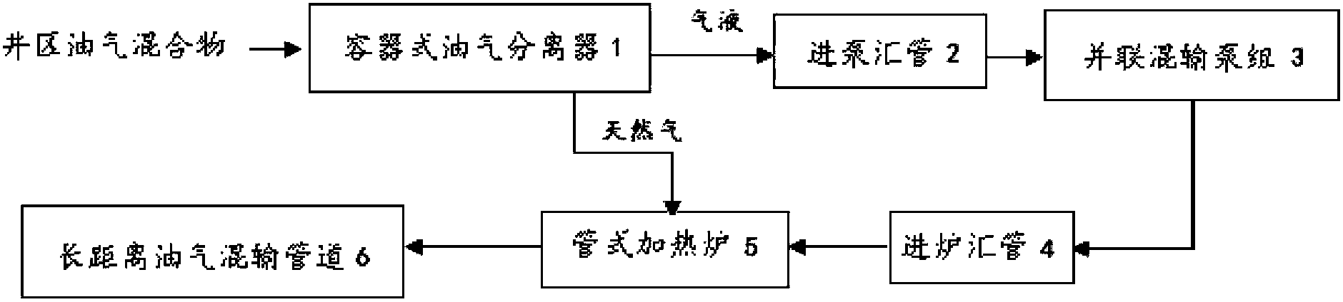
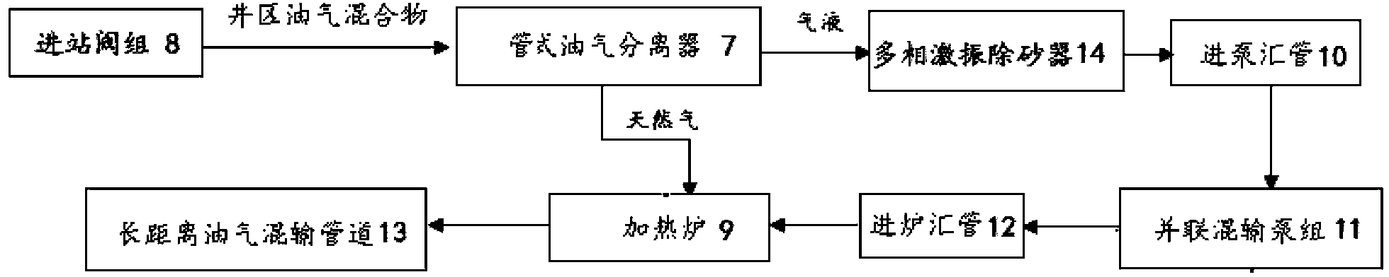
[0030] The oil-gas separator is the key supporting equipment in the oil-gas mixed transportation system, such as figure 1 In the shown oil-gas mixed transportation system, a container-type oil-gas separator 1 is used. The present invention designs a pipe-type oil-gas separator 7, which can replace the container-type oil-gas separator 1 for figure 1 The system shown can also be used for figure 2 The oil-gas mixed transportation system shown. figure 2 In the oil-gas mixed transportation system shown, the inlet end of the pipe-type oil-gas separator 7 is connected to the manifold after the inlet valve group 8 to receive the oil-gas mixture, and part of the natural gas is separated from the oil-gas mixture as the fuel for the heating furnace 9 The 7 outlet ends of the tubular oil-gas separator are divided i...


PUM

PropertyMeasurementUnit
diameteraaaaaaaaaa
diameteraaaaaaaaaa

Abstract

The invention relates to a pressurizing heating oil gas mixing transportation system and method. The system comprises an in-station valve group, a fuel gas separator, an oil gas mixing transportation pump, a pipe type heating furnace and a long-distance oil gas mixing transportation pipe which are sequentially communicated through a pipe. A multi-phase shock excitation sand remover, a multi-phase mixing transportation pump group inlet uniform flow device and a gas liquid separation flow divider. Gas and liquid mixture from an oil field well area enters the pipe type fuel gas separator, a part of natural gas is separated to serve as fuel of the heating furnace, surplus gas liquid mixture enters the multi-phase shock excitation sand remover to be subjected to sand removing, enters the multi-phase mixing transportation pump group inlet uniform flow device to be subjected to uniform flow distribution and is delivered to the gas liquid separation flow divider through the oil gas mixing transportation pump, and the separated liquid enters the pipe type heating furnace to be heated and is mixed with the separated gas to enter the long-distance oil gas mixing transportation pipe. Safe stable high-efficiency operation of the system is guaranteed, service life of devices is prolonged, and project investment, energy consumption, operation maintenance and operation cost are reduced.

Description

technical field [0001] The invention relates to a surface engineering oil and gas gathering and transportation technology in oil exploitation, in particular to a fuel gas oil and gas separator and an oil and gas separation method used in a pressurized heating oil and gas mixed transportation process system. Background technique [0002] At present, in the process of oil and gas gathering and transportation in oilfield surface engineering, more and more pressurized heating oil and gas mixed transportation technology is used. The system and process are as follows: figure 1 Shown: After the oil-gas mixture in the well area is separated by the container-type oil-gas separator 1, the gas-liquid part first passes through the inlet pump manifold 2, is transported through the parallel mixed pump group 3, and then enters the tubular heating furnace through the furnace inlet manifold 4 5 for heating, and finally enters the long-distance oil-gas mixed transportation pipeline 6; while p...

Claims


Application Information

Patent Timeline
Patent Type & Authority Patents(China)
IPC IPC(8): C10L3/10B01D45/02B01D45/04
Inventor 宋承毅杨峰
Owner PETROCHINA CO LTD
Why Eureka
Try Eureka