Rock debris treatment type mud tank capable of flexibly changing cleaning position

A processing type, mud tank technology, applied in the direction of mixer with rotating stirring device, chemical/physical process, dissolution, etc., can solve the problem of debris accumulation and blockage, inconvenient cleaning, etc., to achieve the effect of avoiding blockage and easy replacement

Inactive Publication Date: 2017-07-21
CHENGDU LAIBAO PETROLEUM EQUIP
View PDF6 Cites 0 Cited by
  • Summary
  • Abstract
  • Description
  • Claims
  • Application Information

AI Technical Summary

Problems solved by technology

[0003] The purpose of the present invention is to provide a cuttings treatment type mud tank that can flexibly replace the cleaning position, so as to solve the problem of inconvenient cleaning due to the accumulation of cuttings in the backflow tank in the prior art, and realize the convenient cleaning of the debris accumulated in the backflow tank the goal of

Method used


Image

  • Rock debris treatment type mud tank capable of flexibly changing cleaning position
  • Rock debris treatment type mud tank capable of flexibly changing cleaning position

Examples


Embodiment 1

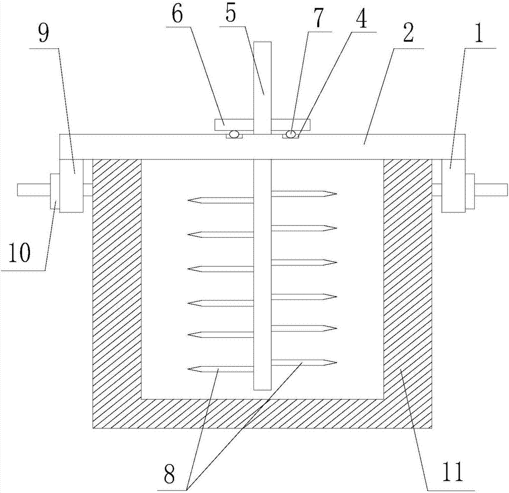
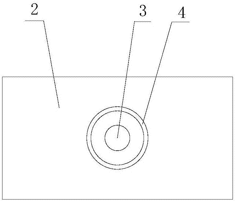
[0021] Such as figure 1 and figure 2 The cuttings treatment type mud tank for flexibly changing the cleaning position as shown is characterized in that it includes a straight plate 2, the opposite ends of the straight plate 2 are respectively fixedly connected with a baffle plate 1, and the center of the straight plate 2 is provided with a circular through hole 3 and a circular An annular groove 4, the groove 4 is concentric with the through hole 3, and the through hole 3 is located inside the ring of the groove 4; also includes a stirring rod 5 passing through the through hole 3; the stirring rod 5 The upper cover is provided with a disc-shaped turntable 6, and the turntable 6 is fixedly connected to the stirring rod 5; the surfaces on both sides of the turntable 6 are perpendicular to the axis of the stirring rod 5, and the surface of the turntable 6 is provided with N rollers 7, N rollers 7 rings are evenly distributed, the turntable 6 is located on the side of the straig...


PUM


Abstract

The invention discloses a rock debris treatment type mud tank capable of flexibly changing the cleaning position. The rock debris treatment type mud tank comprises a straight plate, the two opposite ends of the straight plate are fixedly connected with two baffles correspondingly, a circular through hole and a groove are formed in the center of the straight plate, and the through hole is located in a ring of the groove. The mud tank further comprises a stirring rod penetrating through the through hole. The stirring rod is sleeved with a disk-shaped turntable, the two surfaces of the turntable are perpendicular to the axis of the stirring rod, and N rollers are arranged on the surfaces of the turntable. The turntable is located on the side, provided with the groove, of the straight plate, and the N rollers are located in the groove. A plurality of rod-shaped protrusions are further fixed on the surface of the stirring rod, and the protrusions and the baffles are located on the same side of the straight plate. The baffles are provided with threaded holes, and pushing screws are arranged in the threaded holes and provided with matched nuts. The rock debris treatment type mud tank is used for solving the problem that rock debris is stacked and blocked in a return tank and is not convenient to remove in the prior art, and the purpose of conveniently removing stacked rock debris in the return tank is achieved.

Description

technical field [0001] The invention relates to the field of oil exploitation, in particular to a cuttings treatment type mud tank for flexible replacement of cleaning positions. Background technique [0002] Mud tank, also known as drilling fluid tank and backflow tank, is a tank that passes between the wellhead and the solid control equipment when the drilling fluid flows back from the wellhead to the sedimentation tank or mud tank during the drilling and completion of oil production. It is used to convey the mud with cuttings or formation sand returned from the well. The mud tank is the sampling place for drilling fluid logging, which is of great significance for mud logging. Liquid level sensors are installed in the mud tanks to monitor the amount of drilling fluid returned, so that it is convenient for engineers to judge whether there is overflow, lost circulation or kick, etc. at the first time. Therefore, the liquid level signal measured by the liquid level sensor i...

Claims


Application Information

Patent Timeline
Patent Type & Authority Applications(China)
IPC IPC(8): E21B21/01B01F7/18
CPCE21B21/01B01F27/90B01F2101/28
Inventor 谭正怀
Owner CHENGDU LAIBAO PETROLEUM EQUIP
Why Eureka
Try Eureka