
Crosswind utilized type cooling tower

A cooling tower and cross-wind technology, applied in the direction of water shower coolers, direct contact heat exchangers, heat exchanger types, etc., can solve the problems of cold air backflow, reduced outlet section, uncontrollable direction and wind speed, etc. , to achieve the effect of improving the suction effect and strengthening the suction effect

Inactive Publication Date: 2015-03-04
王卫良
View PDF3 Cites 4 Cited by
  • Summary
  • Abstract
  • Description
  • Claims
  • Application Information

AI Technical Summary

Problems solved by technology

However, due to the existence of environmental crosswinds, as well as the uncontrollability of its direction and wind speed, it has brought great challenges to the economical, safe and stable operation of the unit.
[0003] The environmental side wind will mainly damage the pressure field and flow field environment at the inlet and outlet of the cooling tower, form a vortex flow inside the cooling tower, and deflect the airflow at the outlet of the cooling tower, resulting in a reduction in the outlet section, and even causing cold air to flow backward into the tower, affecting The normal natural ventilation of the tower affects the normal heat transfer of air cooling
At present, the structural optimization of cooling towers at home and abroad is mainly focused on adding deflectors to the air inlet at the bottom of the cooling tower (such as CN201320639660, etc.), optimizing the filling inside the cooling tower (such as CN201310631563, etc.), and adding deflectors to the outlet of the cooling tower (such as CN201310745997 etc.), while there are relatively few studies on the side wall of cooling towers

Method used


Image

  • Crosswind utilized type cooling tower
  • Crosswind utilized type cooling tower
  • Crosswind utilized type cooling tower

Examples


Embodiment 1

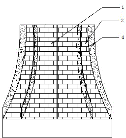
[0018] figure 1 Structural schematic (front view) of a cooling tower utilizing a crosswind with deflectors. The side wind utilizes a cooling tower, including a conventional cooling tower (1) and a diversion baffle (4), and is characterized in that a plurality of diversion baffles are installed at different angles in the circumferential direction on the side wall (2) of the cooling tower. The diversion partitions are installed vertically along the direction of the cooling tower bus. The guide baffles are evenly installed on the side walls around the cooling tower, or concentratedly installed on the side of the cooling tower that suffers from strong winds for a long time. The cross section of the diversion baffle can be designed in the shape of rectangle, trapezoid or triangle.

[0019] A kind of concrete implementation of the present invention is as follows: firstly according to cooling tower characteristic parameter, local environment side wind speed, temperature, sunshine ...

Embodiment 2

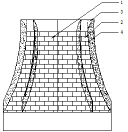
[0023] figure 2 Structural schematic (front view) of a cooling tower for a crosswind utilization with deflectors and deflector crowns. The side wind uses a cooling tower, including a conventional cooling tower (1), a diversion crown (3) and a diversion partition (4), which is characterized in that multiple Diversion partition. The diversion partitions are installed vertically along the direction of the cooling tower bus. The guide baffles are evenly installed on the side walls around the cooling tower, or concentratedly installed on the side of the cooling tower that suffers from strong winds for a long time. The cross section of the diversion baffle can be designed in the shape of rectangle, trapezoid or triangle. A diversion crown is installed on the periphery of the outlet of the cooling tower, its lower edge is installed close to the side wall of the cooling tower, and its outer surface replaces the side wall of the cooling tower covered by it to intersect with the div...

Embodiment 3

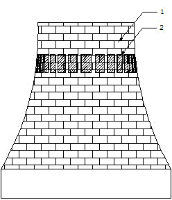
[0028] image 3Structural schematic (front view) of a cooling tower for a crosswind utilization with side windows. The side wind utilizes a cooling tower, including a conventional cooling tower (1) and a side window (5), and is characterized in that: the side window is provided on the cooling side wall. The side window is set at the waist or above the waist, and a backstop damper is installed on the side window.

[0029] A kind of concrete implementation of the present invention is as follows:

[0030] First, select the material of the side window frame, such as plastic, metal, alloy, foam filling material, etc., according to the characteristic parameters of the cooling tower, the local environmental side wind speed, temperature, sunshine and other weather conditions. Then, according to the characteristic parameters of the cooling tower and the wind force, temperature, sunshine and other parameter requirements, optimize the design of the basic data and processing drawings su...


PUM


Abstract

The invention provides a crosswind utilized type cooling tower, and relates to a device for arranging and utilizing environmental crosswind of a power plant. The cooling tower comprises a general cooling tower body, a guide baffle mounted on the sidewall of the cooling tower, a guide crown mounted at an outlet of the cooling tower, and a side window mounted at the waist part or position above the waist part of the cooling tower body. According to the crosswind utilized type cooling tower, the environmental crosswind under a windward side flows through a guide channel consisting of the guide baffle and the sidewall of the cooling tower and is converted into updraft which upwards flows along the sidewall, and then the updraft is returned through the guide crown around the outlet of the cooling tower body to form an inclined updraft withstanding the incoming crosswind stream, so as to resist the direct interference of the environmental crosswind to the air stream from the outlet of the cooling tower body; meanwhile, the inclined updraft meets the incoming crosswind to further guide the hot air from the outlet of the cooling tower body; when the environmental crosswind is increased to reach a degree, a low pressure area of which the pressure is less than the pressure in the tower is formed in the side of the tower, the side window is opened at the same time to enable the updraft in the tower to flow out quickly, and as a result, the ventilating capacity of the cooling tower is improved.

Description

technical field [0001] The invention belongs to the industrial cooling fields of power generation, metallurgy, and chemical industry, and relates to circulating water cooling equipment, in particular to an energy-saving and safe natural ventilation cooling equipment for organizing and utilizing environmental side winds. Background technique [0002] The cooling tower is the key equipment of the indirect air cooling unit or the closed circulation water wet cooling unit of the power plant. It is a necessary condition for establishing the vacuum of the steam turbine and taking away the heat source at the cold end. However, due to the existence of environmental crosswinds and the uncontrollability of its direction and wind speed, it has brought great challenges to the economical, safe and stable operation of the unit. [0003] The environmental side wind will mainly damage the pressure field and flow field environment at the inlet and outlet of the cooling tower, form a vortex f...

Claims


Application Information

Patent Timeline
IPC IPC(8): F28F25/12
Inventor 王卫良
Owner 王卫良
Learn More