
Manufacturing method of metasurface optical element

A technology for optical elements and manufacturing methods, which is applied in the field of semiconductors, and can solve the problems of affecting the use effect of metasurface optical elements, increasing the difficulty of designing metasurface optical elements, and the relative refractive index of metasurface optical elements.

Pending Publication Date: 2022-08-09
天津山河光电科技有限公司
View PDF0 Cites 0 Cited by
  • Summary
  • Abstract
  • Description
  • Claims
  • Application Information

AI Technical Summary

Problems solved by technology

[0004] However, due to the relatively small difference between the refractive index of the protective material and the refractive index of the nanomaterial, the relative refractive index of the metasurface optical element is relatively small, which increases the difficulty of designing the metasurface optical element and affects the use of the metasurface optical element. Effect

Method used


Image

  • Manufacturing method of metasurface optical element
  • Manufacturing method of metasurface optical element
  • Manufacturing method of metasurface optical element

Examples


Embodiment Construction

[0042] The technical solutions of the embodiments of the present application will be described below with reference to the accompanying drawings in the embodiments of the present application.

[0043] The terms used in the following embodiments of the present application are only for the purpose of describing specific embodiments, and are not intended to be used as limitations of the present application. As used in the specification of this application and the appended claims, the singular expressions "a," "an," "the," "above," "the," and "the" are intended to also Plural expressions are included unless the context clearly dictates otherwise. It should also be understood that although the terms first, second, etc. may be used in the following embodiments to describe a certain class of objects, the objects should not be limited to these terms. These terms are only used to distinguish specific objects of this class of objects. For example, the terms first, second, etc. may be ...


PUM


Abstract

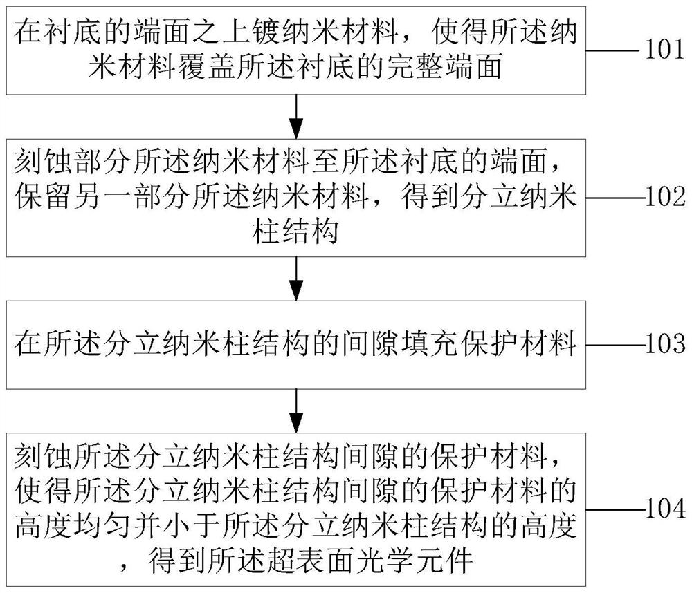
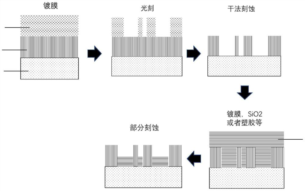
The embodiment of the invention discloses a manufacturing method of a metasurface optical element, and the method comprises the steps: plating a nanometer material on the end face of a substrate, and enabling the nanometer material to cover the complete end face of the substrate; etching a part of the nanometer material to the end face of the substrate, and reserving the other part of the nanometer material to obtain a discrete nanometer column structure; filling a gap of the discrete nano-column structure with a protective material; and etching the protective material in the gaps of the discrete nano-column structures, so that the height of the protective material in each gap is uniform and less than the height of the discrete nano-column structures, and obtaining the metasurface optical element. The gaps of the discrete nano-column structures are plated with the protective material, so that the mechanical stability of the nano-column structures is enhanced; the height of the protection material is controlled to be smaller than that of the nanorod, and the relative refractive index difference between the nanorod structure exposed on the upper half part and the surrounding environment is ensured; bonding a glass wafer at the top of the nanorod to protect the nanorod from being damaged by the outside; the glass wafer is supported with a support material against wear due to contact with the nanorods.

Description

technical field [0001] The embodiments of the present application relate to the technical field of semiconductors, and in particular, to a method for fabricating a metasurface optical element. Background technique [0002] The metasurface optical element consists of a substrate and discrete nano-column structures arranged on the surface of the substrate. Through different materials, different structures, and / or different arrangements between the discrete nano-column structures, a variety of different Therefore, metasurface devices are often used in display devices and optical computing devices. [0003] In the process of using the metasurface optical element, the metasurface optical element may be bumped, and the mechanical stability of the nanopillar itself may be poor, or the nanopillar and the substrate may not be combined due to the different materials of the nanopillar and the substrate. The phenomenon of compactness makes the nanopillars on the surface of the substrat...

Claims


Application Information

Patent Timeline
IPC IPC(8): B81C1/00B81C3/00G03F7/00B82Y20/00B82Y40/00
CPCG03F7/0005B81C1/00111B81C3/002B82Y20/00B82Y40/00B81C2201/013G02B1/14G02B1/002
Inventor 孙磊秦飞李向平
Owner 天津山河光电科技有限公司
Learn More