
Cross-line pay-off device

A pay-off device and cross-line technology, applied in the direction of overhead lines/cable equipment, etc., can solve the hidden dangers of operators below, damaged wire insulation, electric shock accidents, etc., to achieve convenient and fast use, avoid wear and tear, and protect personnel safety Effect

Active Publication Date: 2021-03-16
QINGYUAN POWER SUPPLY BUREAU OF GUANGDONG POWER GRID CO LTD
View PDF12 Cites 2 Cited by
  • Summary
  • Abstract
  • Description
  • Claims
  • Application Information

AI Technical Summary

Problems solved by technology

Moreover, some construction workers do not take any protective measures for the lower layer wires, directly press the upper layer wires on the surface of the lower layer wires, and drag them; or use PVC sleeves to cover the lower layer wires and drag them, which cannot effectively protect the lower layer wires.
Moreover, in the existing way of striding over the wires, during the construction process, the upper conductors do not hold the upper conductors tightly, causing the upper conductors to slide down and press on the lower conductors, and the insulation of the conductors is damaged, thereby causing damage to the operators below. Potential safety hazards, and even electric shock accidents

Method used


Image

  • Cross-line pay-off device
  • Cross-line pay-off device
  • Cross-line pay-off device

Examples


Embodiment 1

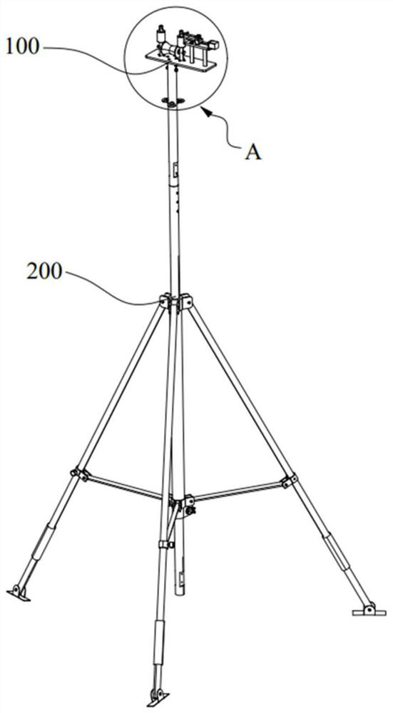
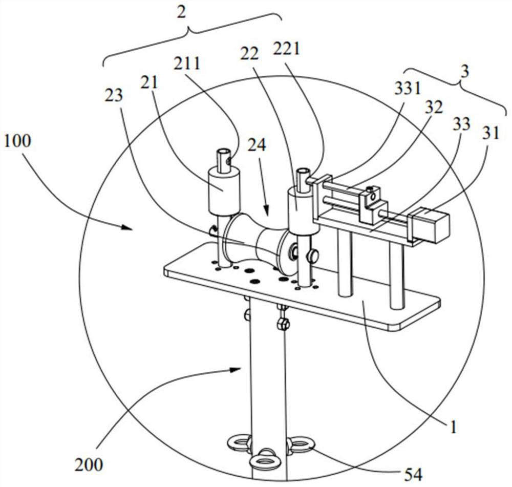
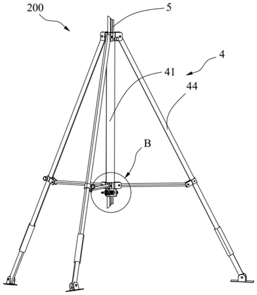
[0042] Such as Figure 1-7 As shown, the specific content of this embodiment is described in detail. Such as Figure 1-2 As shown, this embodiment provides a cross-line pay-off device, which is used for erecting the upper-layer wire across the lower-layer wire. The cross-line pay-off device includes a wire release mechanism 100 and a lifting mechanism 200. The guide unit 2 and the connection unit 3, the base 1 is in the shape of a long plate, the guide unit 2 is arranged above the base 1, the upper layer wires are configured to pass through the guide unit 2, and the connection unit 3 is also arranged above the base 1 , and is located on one side of the guide unit 2, the connecting unit 3 includes a first driving device 31 and a connecting piece 32, the output end of the first driving device 31 is connected to the connecting piece 32, and the first driving device 31 can drive the connecting piece 32 and the connecting piece 32 The guide unit 2 cooperates to limit the upper laye...

Embodiment 2

[0055] This embodiment provides an over-the-line pay-off device. Compared with Embodiment 1, the basic structure of the over-the-line pay-off device provided by this embodiment is the same as that of Embodiment 1, and only the splicing of the lifting tube 5 is different. The embodiment does not repeat the same structure as that of the first embodiment.

[0056] In this embodiment, one end of the lift tube 5 provided with an intermediate connector 52 is provided with an external thread, and the other end of the lift tube 5 is provided with an internal thread, and the adjacent lift tubes 5 can be screwed together to realize the length of the lift tube 5. extension.


PUM


Abstract

The invention discloses a cross-line pay-off device, which belongs to the technical field of power equipment and comprises a pay-off mechanism and a lifting mechanism, the pay-off mechanism comprisesa base, a guide unit and a connecting unit, the guide unit is arranged on the base, and an upper-layer wire is configured to penetrate through the guide unit; the connecting unit is arranged on the base and located on one side of the guiding unit, the connecting unit comprises a first driving device and a connecting piece, the output end of the first driving device is connected with the connectingpiece, and the first driving device can drive the connecting piece to be matched with the guiding unit so as to limit the upper-layer wire; the lifting mechanism is connected with the base and can enable the pay-off mechanism to move in the vertical direction. The upper-layer wire is arranged in the guide unit in a penetrating mode, and the connecting piece is matched with the guide unit, so thatthe upper-layer wire is stably limited and cannot fall off from the pay-off mechanism; the lifting mechanism drives the base to move in the vertical direction, so that the upper-layer wire is liftedaway from the lower-layer wire, and the lower-layer wire is prevented from being abraded.

Description

technical field [0001] The invention relates to the technical field of electric equipment, in particular to an over-the-line pay-off device. Background technique [0002] When crossing over 0.4kV low-voltage wires and erecting 10kV conductors or when erecting other conductors over overhead communication lines, the lower conductors will be dragged during the process of unwinding the upper conductors. And now some construction workers do not do any protective measures to the lower conductor, directly press the upper conductor on the surface of the lower conductor, and drag it; Moreover, in the existing way of striding over the wires, during the construction process, the upper conductors do not hold the upper conductors tightly, causing the upper conductors to slide down and press on the lower conductors, and the insulation of the conductors is damaged, thereby causing damage to the operators below. Potential safety hazard, even cause electric shock accident. [0003] For thi...

Claims


Application Information

Patent Timeline
IPC IPC(8): H02G1/02
CPCH02G1/02
Inventor 黄章娉温振宇梁升锋麦嘉颖曾婧雯黄晓晴吴忠奇李雪玲朱振杰陈智莹汤桂莹区婉媚钟冠杰雷玉琼廖伟杰曾浩郑浩均
Owner QINGYUAN POWER SUPPLY BUREAU OF GUANGDONG POWER GRID CO LTD
Learn More