
Engine control mechanism

A control mechanism and engine technology, applied in the direction of engine control, electric engine control automatic control, automatic control, etc., can solve the problems of delay, limited maneuverability, low discharge pressure of oil pump, etc.

Inactive Publication Date: 2015-02-11
AISIN SEIKI KK
View PDF11 Cites 4 Cited by
  • Summary
  • Abstract
  • Description
  • Claims
  • Application Information

AI Technical Summary

Problems solved by technology

[0006] In addition, when it is desired to operate the VVT ​​on the exhaust side, since the discharge pressure of the oil pump is low when the engine output is low, there will be a slight delay in the phase switching control of the VVT.
[0007] As such, in the related art, even if it is desired to increase the engine output from a state where the engine speed is low, it takes a lot of time to increase the torque, and there is a limit in improving the drivability

Method used


Image

  • Engine control mechanism
  • Engine control mechanism
  • Engine control mechanism

Examples


Embodiment 1

[0062] Figure 7 It is an explanatory diagram showing how each part changes when the operating state of the engine E is a transitional operating state.

[0063] Figure 7(1) Accelerator opening degree, (2) Intake valve opening degree, (3) Ignition timing, (4) Exhaust side VVT ​​phase, (5) Intercooler outlet boost pressure, (6) ) front-rear acceleration of the vehicle, (7) intake side VVT ​​phase, (8) engine load, and (9) engine speed. In the figure, a solid line indicates an example of engine control according to the present embodiment, and a dashed-dotted line indicates an example of engine control capable of realizing the Atkinson cycle operation of the related art.

[0064] Even though the engine is transitioning from the Atkinson cycle state to the high output state, it is not assumed in this paper that the accelerator is heavily depressed. Conversely, the engine control mechanism is effective when overrunning from the low-load Atkinson operating range where practical f...

Embodiment approach

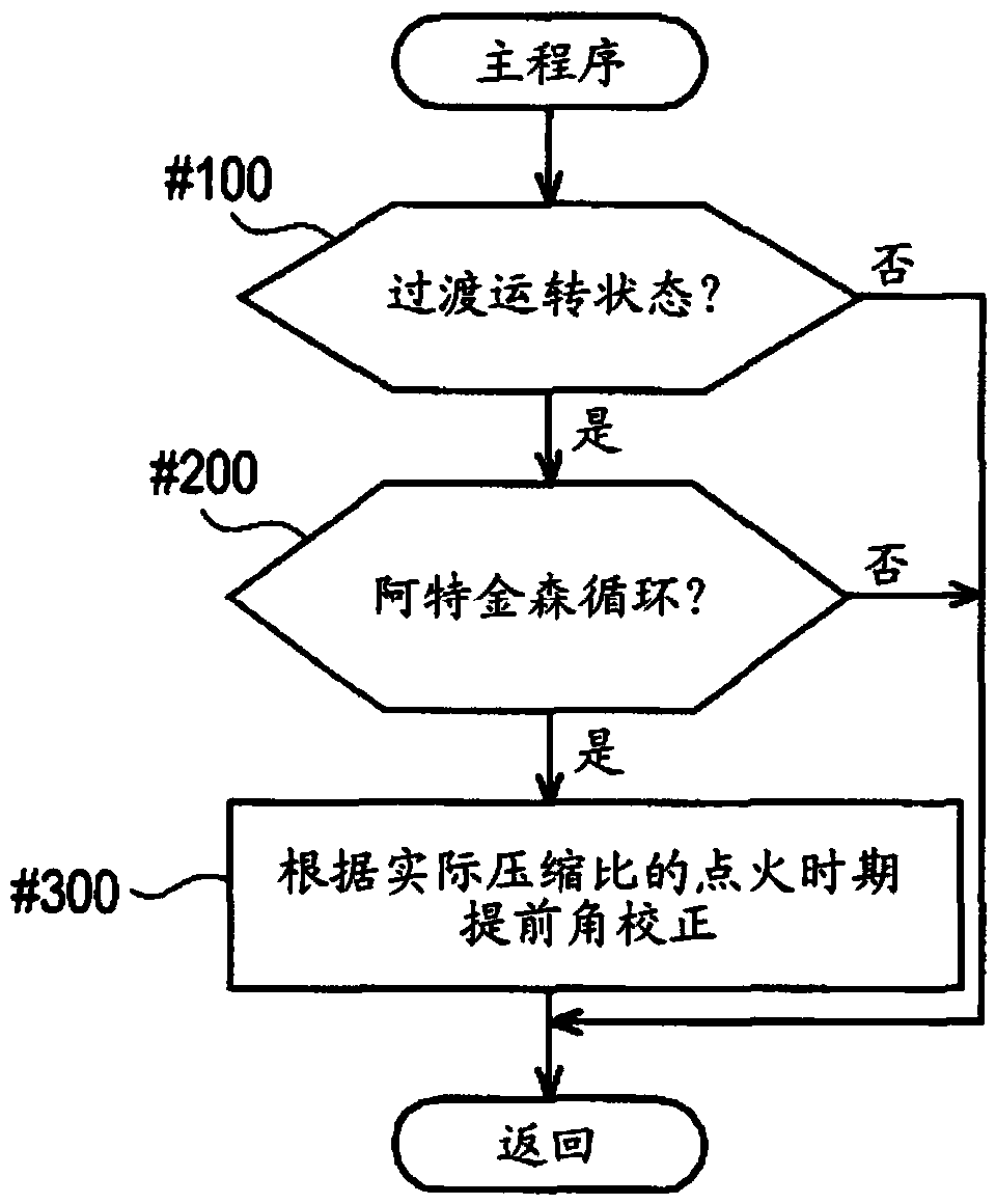
[0075] The ignition timing advance angle correction control, VVT hydraulic oil pressure boost correction control, and exhaust side VVT ​​5 advance angle correction control described in the above-mentioned embodiments are as follows: Image 6 The illustration can also be constituted by a flowchart. For example, after the transient operation determination (step 130) and the Atkinson cycle determination (step 230) by the ECU 6a, the ignition timing advance angle correction (step 330) and the determination of whether the actual VVT phase has reached the target VVT phase are performed (step 430); when the actual VVT phase is less than the target VVT phase, perform boost correction of VVT hydraulic oil pressure (step 530), and determine whether the actual supercharging pressure reaches the target supercharging pressure (step 630); The advance angle correction of the exhaust side VVT ​​5 is performed when the actual supercharging pressure is smaller than the target supercharging pres...


PUM


Abstract

An engine control mechanism includes intake and exhaust valves that opens and closes a combustion chamber of an engine to be driven with gasoline. The engine control mechanism includes: an intake-side VVT including first driving-side and driven-side rotary bodies, and capable of setting a valve opening / closing timing of the intake valve such that a relative phase of the first driven-side rotary body is set to an intermediate lock phase at the time of starting of the engine, and the relative phase is set to a more retarded side than the intermediate lock phase after the starting; an exhaust-side VVT including second driving-side and driven-side rotary bodies, and setting a valve opening / closing timing of the exhaust valve such that a relative phase of the second driven-side rotary body is set to any phase between the most advanced phase and the most retarded phase; a control unit advance-controlling the ignition timing when an operational state has shifted from an Atkinson cycle state to a transient operational state; and an ignition timing changing mechanism in which the driving is controlled by the control unit.

Description

technical field [0001] The present invention relates to an engine control mechanism provided with an intake-side variable valve timing mechanism (VVT) capable of setting valve opening / closing of an intake valve and an exhaust-side VVT period so that the relative phase of the driven-side rotary body relative to the driving-side rotary body is set at an intermediate lock phase between the most advanced phase and the most retarded phase at the time of engine start using a gasoline drive, and the relative phase is changed after the engine is started. The phase is set to a phase on the lag side than the intermediate lock phase, and the exhaust side VVT ​​sets the valve opening / closing timing of the exhaust valve so that the relative phase of the driven side rotating body relative to the driving side rotating body Set any phase between the most advanced phase and the most lagging phase. Background technique [0002] In the related art, as such an engine control mechanism, for exa...

Claims


Application Information

Patent Timeline
Patent Type & Authority Applications(China)
IPC IPC(8): F02D13/02F02P5/145
CPCF02P5/1521F01L2001/34496F01L2001/34466F02D2041/001F02P5/1523F02D41/0007F01L1/3442F02D13/0269F01L2001/34423F01L2001/34463F02P5/1551F02P5/045F01L2001/34456F02D13/0219F02P5/142F02D2013/0292Y02T10/12Y02T10/40
Inventor 金子雅昭
Owner AISIN SEIKI KK
Learn More