Testing device for resin matrix composite material heat mold pressing curing deformation and manufacturing and using method thereof
A composite material, curing deformation technology, applied in measurement devices, optical devices, special recording/indicating devices, etc., can solve the problems of ineffective transmission of monitoring signals, difficulty in detaching from fully rigid molds, and fragile and easily broken gate areas. Avoid large artificial deformation, facilitate demolding, and avoid direct contact
- Summary
- Abstract
- Description
- Claims
- Application Information
AI Technical Summary
Problems solved by technology
Method used
Image
Examples
Embodiment 1
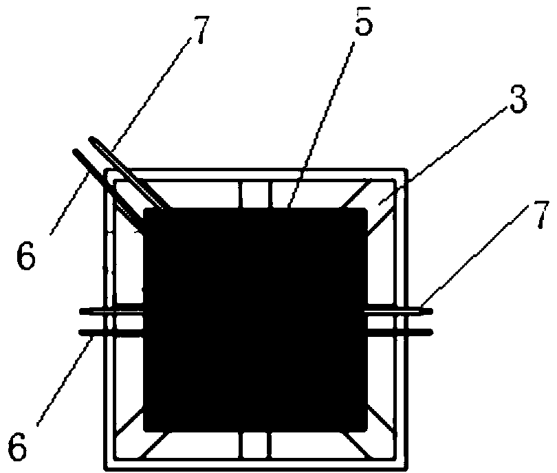
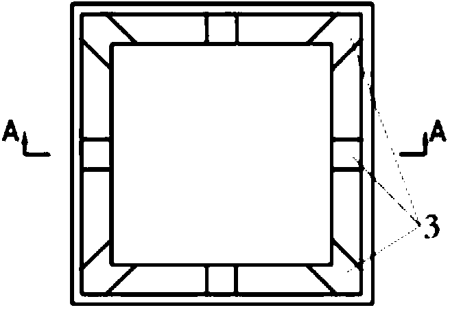
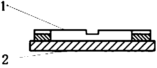
[0041] A test device for hot molding and curing deformation of resin-based composite materials, including resin-based composite material prepregs 5 laid in the mold and FBG sensors arranged in the middle, and multiple FBG sensors are laid in the same prepreg layup or Lay FBG sensors in multiple prepreg layers, lay FBG sensors along the fiber axis direction on the nth layer (n>1) as a strain sensor 6, and lay a reference sensor 7 for temperature compensation on the n+1th layer, The mold side wall frame plate is provided with a lead wire groove 3, and the surface of the mold side wall frame plate and the lead wire groove is covered with a high temperature resistant polymer film 4, and the lead wire of the sensor is drawn out from the lead wire groove 3 of the mold side wall frame plate 1. The signal receiver is switched on.
[0042] Preparation and use method:
[0043] (1) Process lead grooves with a width of 10mm and a depth of 1.5mm at the middle position of each side and at ...
Embodiment 2
[0053] A test device for hot molding and curing deformation of resin-based composite materials, including resin-based composite material prepregs 5 laid in the mold and FBG sensors arranged in the middle, and multiple FBG sensors are laid in the same prepreg layup or FBG sensors are respectively laid in multiple prepreg layups, FBG sensors are laid on the nth layer (n>1) along the direction of the fiber axis as strain sensors 6, and reference sensors 7 for temperature compensation are also laid on the nth layer. The side wall frame plate is provided with a lead groove 3, and the surface of the mold side wall frame plate and the lead groove is covered with a high temperature resistant polymer film 4, and the lead wire of the sensor is drawn out from the lead groove 3 of the mold side wall frame plate 1 to communicate with the signal. The receiver is switched on.
[0054] Preparation and use method:
[0055] (1) Process lead grooves with a width of 10 mm and a depth of 2.0 mm a...
Embodiment 3
[0065] A test device for hot molding and curing deformation of resin-based composite materials, including resin-based composite material prepregs 5 laid in the mold and FBG sensors arranged in the middle, and multiple FBG sensors are laid in the same prepreg layup or FBG sensors are respectively laid in multiple prepreg layups, FBG sensors are laid along the fiber axis direction on the nth layer (n>1) as strain sensors 6, and reference sensors 7 for temperature compensation are laid on the n-1th layer, The mold side wall frame plate is provided with a lead wire groove 3, and the surface of the mold side wall frame plate and the lead wire groove is covered with a high temperature resistant polymer film 4, and the lead wire of the sensor is drawn out from the lead wire groove 3 of the mold side wall frame plate 1. The signal receiver is switched on.
[0066] Preparation and use method:
[0067] (1) Process lead grooves with a width of 10 mm and a depth of 2.0 mm at the middle p...
PUM
 Abstract
Description
Claims
Application Information
 - R&D
- Intellectual Property
- Life Sciences
- Materials
- Tech Scout
- Unparalleled Data Quality
- Higher Quality Content
- 60% Fewer Hallucinations
Browse by: Latest US Patents, China's latest patents, Technical Efficacy Thesaurus, Application Domain, Technology Topic, Popular Technical Reports.
© 2025 PatSnap. All rights reserved.Legal|Privacy policy|Modern Slavery Act Transparency Statement|Sitemap|About US| Contact US: help@patsnap.com


