Up-draught biomass gasifier capable of heating fuel gas

A biomass and gasification furnace technology, applied in the manufacture of combustible gas, petroleum industry, etc., can solve the problems of the calorific value reduction of biomass hot gas, affecting the gasification furnace, liquid tar difficult to handle, etc., to achieve dust reduction and good filtration The effect of action

Active Publication Date: 2015-01-28
上海艾耐基科技股份有限公司
View PDF5 Cites 2 Cited by
  • Summary
  • Abstract
  • Description
  • Claims
  • Application Information

AI Technical Summary

Problems solved by technology

The up-suction biomass gasifier will produce more tar and some dust during gasification, the gas generated by the up-suction gasifier must pass through the material layer, the temperature of the gas will be lower, and the gas outlet is generally gasified The top or upper side of the furnace, so that the hot gas coming out of the gasifier often has a large amount of gaseous tar condensed into liquid tar in the pipeline due to the low temperature, which will cause the biomass gasification equipment to not operate normally, and the liquid tar is difficult to handle At the same time, due to the precipitation of tar, the calorific value of the biomass heat gas decreases; when there is a lot of dust, it will also affect the normal operation of the gasifier
This problem cannot be well solved by the current updraft biomass gasification technology.

Method used


Image

  • Up-draught biomass gasifier capable of heating fuel gas

Examples


Embodiment Construction

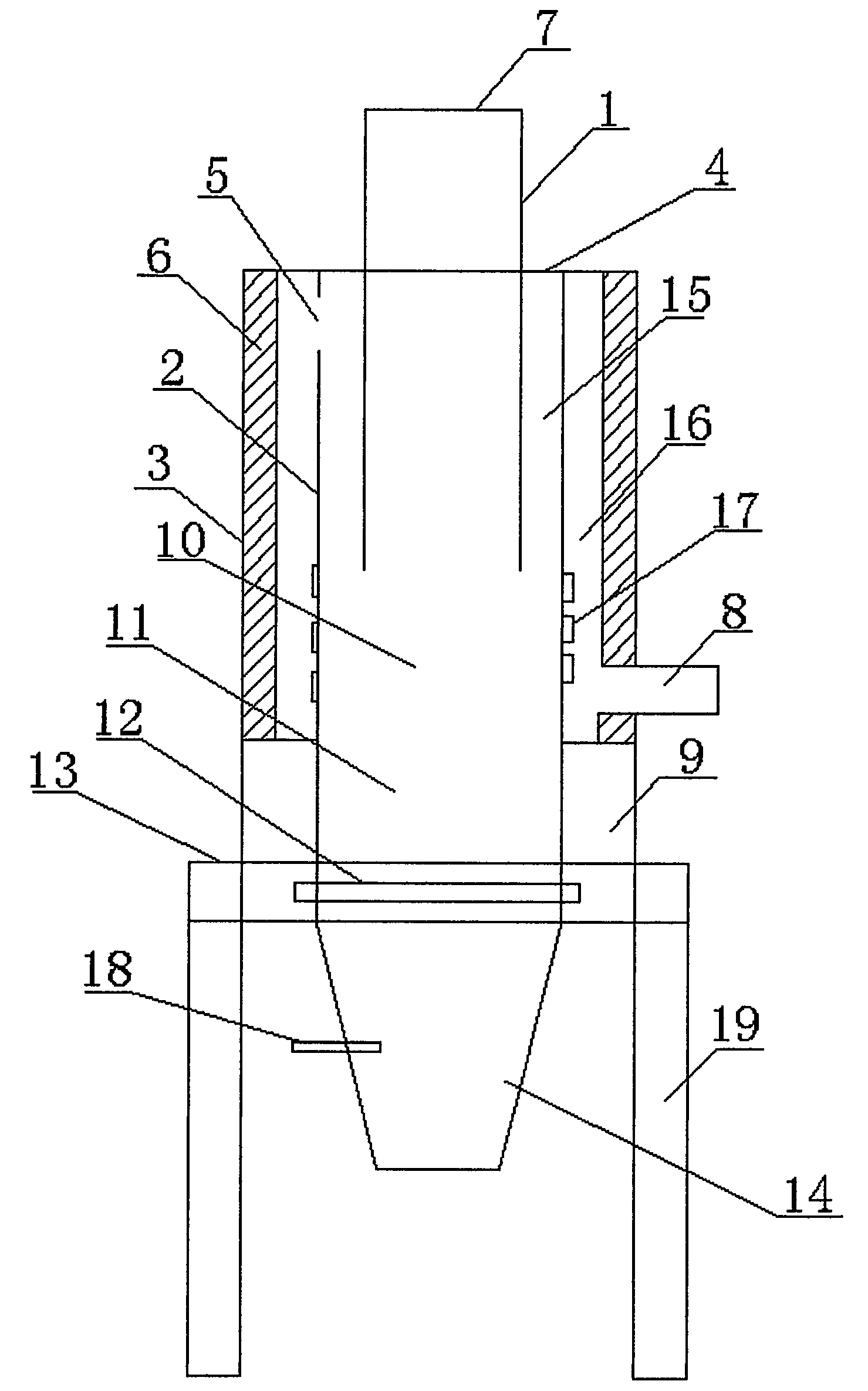
[0012] In order to make the technical means, creative features, goals and effects achieved by the present invention easy to understand, the present invention will be further described below in conjunction with specific illustrations.

[0013] Such as figure 1 As shown, the gasifier includes an outer cylinder 3, a middle cylinder 2, an inner cylinder 1, the upper part of the inner cylinder 1 is a feed port 7, the upper part of the outer cylinder 3 has a cover plate 4, and the inner side of the outer cylinder 3 has a Insulation layer 6, water-cooled jacket 9 at the lower part of outer cylinder 3, gas outlet 8 at the middle and lower part of the outer cylinder, middle cylinder 2 connected to the inner side of water-cooled jacket 9, upper part of middle cylinder 2 connected with cover plate 4, middle cylinder The upper part of the body 2 has one or several air vents 5, the outer side of the middle cylinder 2 has heat transfer fins 17, the fire grate 12 is located at the lower part...


PUM


Abstract

The invention discloses an up-draught biomass gasifier capable of heating a fuel gas. The up-draught biomass gasifier capable of heating the fuel gas comprises an outer barrel, a middle barrel and an inner barrel. Fuel gas channels are formed among the barrels; the fuel gas generated by gasification flows to a fuel gas outlet through the fuel gas channels; heat transfer fins are disposed at the outside of the lower part of the middle barrel; and the fuel gas outlet is arranged at the lower part of the outer barrel. The temperature of the lower side of the middle barrel is relatively high, so that the fuel gas passing through the lower side of the middle barrel is heated continuously; the fuel gas can be kept at a relatively high temperature; tar in the fuel gas always exists in a gas state; and the problem of tar separation is overcome. Although an initial temperature of the fuel gas is reduced by increasing a material layer, the low-temperature fuel gas is heated to the relatively high temperature by the lower part of the middle barrel, so that the material layer of the gasifier can be thickened, thereby playing a better filtration effect for the fuel gas generated by the gasification and reducing generation of dust. The gasifier can keep the generated fuel gas at the relatively high temperature and reduce the generation of dust, and can solve corresponding problems existing in conventional up-draught biomass gasifiers.

Description

technical field [0001] The invention relates to industrial gasification equipment, in particular to an updraft biomass gasification furnace capable of heating gas. Background technique [0002] In recent years, many cities and regions in my country have experienced frequent smog weather, and PM2.5 in many places has continued to exceed the standard. Serious air pollution has sounded the alarm for the industrial development path of "high pollution, high energy consumption, and high emissions" that my country has been following for many years. Among them, air pollution caused by coal-fired industrial boiler emissions is an important reason. Reduce the use of fossil energy such as coal and oil, and seek and utilize clean energy, which can reduce the degree of air pollution and PM2.5 indicators. [0003] Biomass energy is recognized as renewable and clean energy by countries all over the world. There are a large amount of crop straw and forestry waste in my country every year,...

Claims


Application Information

Patent Timeline
Patent Type & Authority Applications(China)
IPC IPC(8): C10J3/20C10J3/84
CPCC10J3/20C10J3/84
Inventor 刘新续
Owner 上海艾耐基科技股份有限公司
Why Eureka
Try Eureka