
Adjustable tool for machining outer cylindrical surface and using method thereof

A technology for machining tools on the outer cylindrical surface, which is applied in the direction of manufacturing tools, metal processing equipment, metal processing machinery parts, etc., can solve the problems of complex structure, high price, low efficiency, etc., to increase the rough machining area, improve efficiency, improve The effect of applicability

Active Publication Date: 2017-07-07
宁波东力股份有限公司
View PDF7 Cites 0 Cited by
  • Summary
  • Abstract
  • Description
  • Claims
  • Application Information

AI Technical Summary

Problems solved by technology

Limited to the structure, machining with boring machines and milling machines can only be processed by the differential compensation method, which cannot guarantee the design accuracy, and can only be used for rough machining, and the efficiency is extremely low; similar tools on the market are often complex in structure and poor in versatility, and most of them are special tools. high price

Method used


Image

  • Adjustable tool for machining outer cylindrical surface and using method thereof
  • Adjustable tool for machining outer cylindrical surface and using method thereof
  • Adjustable tool for machining outer cylindrical surface and using method thereof

Examples


Embodiment 1

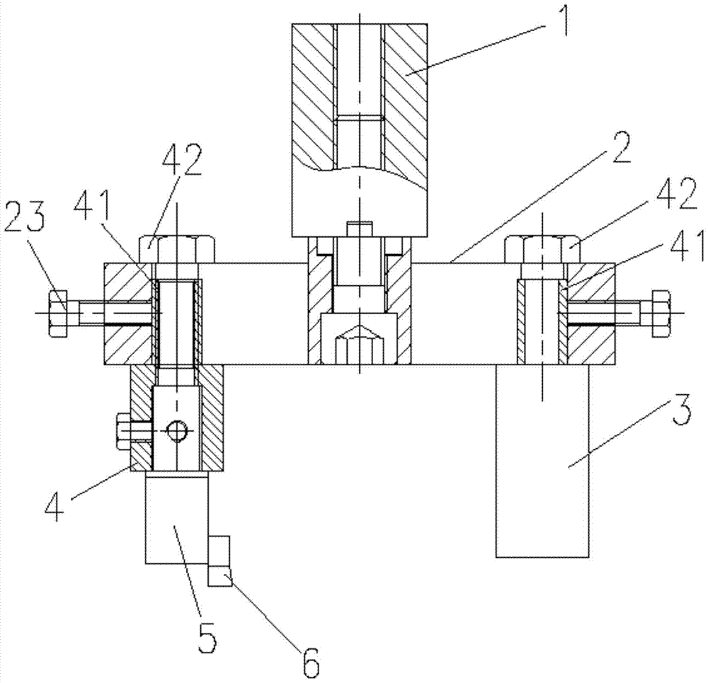
[0027] Such as figure 1 Shown, a kind of adjustable outer cylindrical surface processing cutter comprises a collet connecting rod 1, a slide block 2, a balance weight 3, a cutter head connecting rod 4, a tool holder 5 and a blade 6; One end of rod 1 is connected to the main shaft of the machine tool through a powerful collet handle, and the other end is fixedly connected to the middle of slider 2; one end of cutter head connecting rod 4 is fixedly installed on one end of slider 2 through fixing bolt 42, and the balance weight 3 is fixed and installed through fixing bolt 42 At the other end of the slide block; the other end of the cutter head connecting rod 4 is fixedly connected with a tool holder 5 by a bolt, and a blade 6 is fixedly connected with the tool holder 5, and the blade 6 is rotated towards the axis of the tool.

[0028] The size of the outer circle of the spring clip joint 1 can be adjusted according to the size of the tool holder of different powerful collets on ...

Embodiment 2

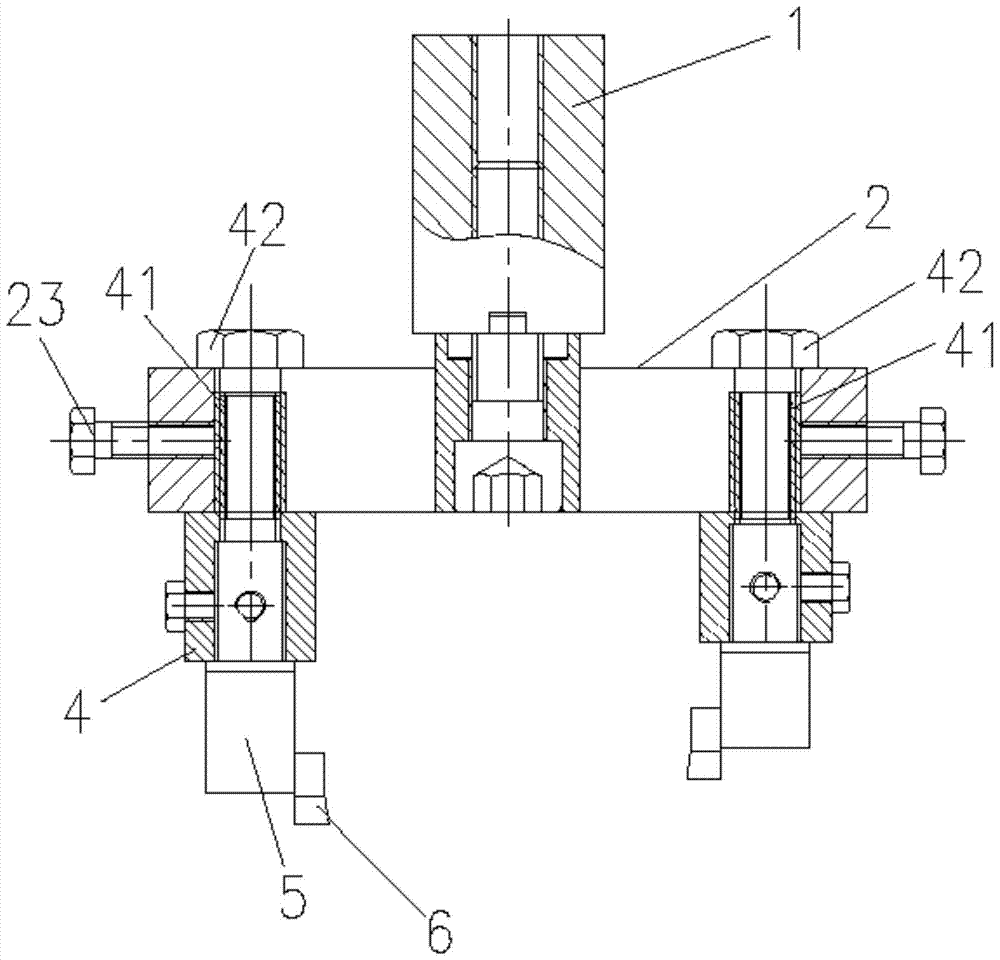
[0035] Such as figure 2 As shown, an adjustable outer cylindrical surface processing tool includes a collet connecting rod 1, a slider 2, two cutter head connecting rods 4, two tool clips 5 and two blades 6; one end of the collet connecting rod 1 The tool handle of the machine tool is connected to the main shaft of the machine tool through a strong chuck, and the other end is fixedly connected to the middle of the slider 2; one end of the two cutter head rods 4 is relatively fixed and installed on both ends of the slider 2 through fixing bolts 42, and the other ends of the two cutter head rods 4 The two tool holders 5 are fixedly connected by bolts, and the two tool holders 5 are fixedly connected with two blades 6, and each blade 6 faces the axis of rotation of the tool.

[0036] When performing rough machining, the balance weight 3 can be replaced by the cutter head connecting rod 4, and then the cutter holder 5 and the blade 6 are connected, and the two blades process the ...


PUM


Abstract

The invention discloses an adjustable tool for machining outer cylindrical surface and its use method. The tool includes a spring collet connecting rod, a slide block, a balance weight, a cutter head connecting rod, a tool holder and a blade; the spring collet One end of the connecting rod is connected to the main shaft of the machine tool through a strong chuck handle, and the other end is fixedly connected to the middle of the slider; one end of the connecting rod of the cutter head is fixed on one end of the slider through a fixing bolt, and the balance block is fixed on the other end of the slider through a fixing bolt; The other end of the connecting rod of the cutter head is fixedly connected to a tool holder through a fixing bolt, and a blade is fixedly connected to the tool holder, and the blade faces the axis of rotation of the cutter; the above-mentioned adjustable outer cylindrical surface processing tool, wherein the balance weight can be connected Combination replacement for rod, cartridge and blade. The invention has simple structure and good versatility, can be used to complete the machining of the outer circle of shafts, and has high machining accuracy.

Description

technical field [0001] The invention relates to an outer cylindrical surface processing tool, in particular to an adjustable outer cylindrical surface processing tool and a use method thereof. Background technique [0002] The planet carrier in the planetary transmission is composed of a web and a shaft used to support multiple planetary wheels. The shaft protrudes from the web and is integrated with the web. The shaft and the center of rotation of the planet carrier are not on the same center line, and each planetary gear revolves around the center of the planet carrier while rotating on its own shaft, and meshes with an inner ring gear and a sun gear. The force is uniform and stable, so the rotation center of each shaft is required to be accurately positioned relative to the revolution center line (planet carrier rotation center). The planetary shaft part is used as the bearing installation positioning surface, and the surface roughness is not greater than Ra1.6, and the s...

Claims


Application Information

Patent Timeline
Patent Type & Authority Patents(China)
IPC IPC(8): B23D79/00B23Q3/12
Inventor 吴文忠李蕾王聪吴民强
Owner 宁波东力股份有限公司
Learn More