
Measurement method of rock core gas logging permeability

A technology of gas permeability measurement and measurement method, which is applied in the field of core gas measurement permeability measurement, can solve problems such as difficult measurement, low data accuracy, and inaccuracy, and achieve inaccurate measurement, high measurement efficiency, and reliable results Effect

Active Publication Date: 2015-01-07
CHINA UNIV OF PETROLEUM (BEIJING)
View PDF10 Cites 6 Cited by
  • Summary
  • Abstract
  • Description
  • Claims
  • Application Information

AI Technical Summary

Problems solved by technology

This method is relatively reliable and has many applications, but the operation is more complicated, the measurement time is long and the stability of the data is affected by many factors.
In the steady-state method, it is very difficult and not accurate enough to measure the fluid flow, especially the small flow of low-permeability rocks
[0005] Steady-state gas permeability measurement method is a common method for measuring rock core permeability at present, which mainly has the following disadvantages: the equipment is huge, not only needs to be equipped with nitrogen or helium gas source, but also requires a huge constant pressure chamber and constant pressure control device, which is inconvenient Field measurement; the pressure difference between the upstream and downstream constant pressure chambers cannot be strictly controlled, and a pressure feedback control device needs to be installed between the upstream and downstream to ensure that the pressure difference between the inlet and outlet of the core is constant, and it takes too long to achieve equilibrium; gas flowmeters generally use soap bubbles Flow meter or ball rise height measurement, due to the compressibility and viscosity of gas, the accuracy of the data measured by the above equipment is low
[0007] The unsteady-state method calculates the core permeability by measuring the change of pressure with time, which avoids the disadvantage of inaccurate gas flow measurement. However, due to the need for gas source, the equipment is relatively large, which is not suitable for field operations, and continuous measurement is required. It takes time to calculate the core permeability. If the gas flow is not stable, the measurement effect of the device is not good.

Method used


Image

  • Measurement method of rock core gas logging permeability
  • Measurement method of rock core gas logging permeability
  • Measurement method of rock core gas logging permeability

Examples


Embodiment 1

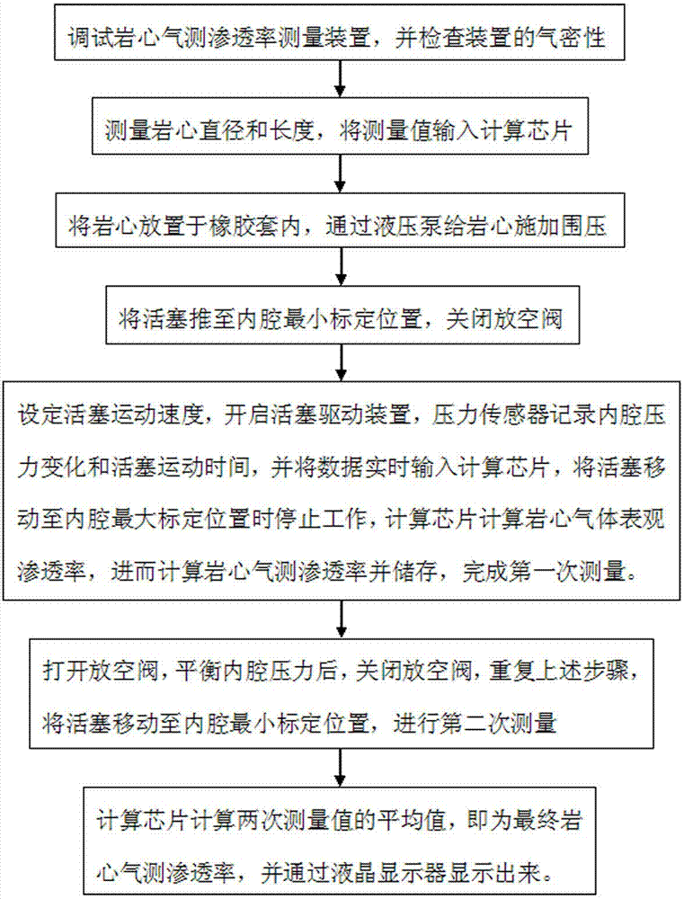
[0114] Such as figure 1 As shown, a core gas permeability measurement method includes the following steps:

[0115] (1) Debug the core gas permeability measurement device and check the air tightness of the measurement device;

[0116] (2) Measure the diameter and length of the core, and input the measured value into the calculation chip;

[0117] (3) Place the core in the rubber sleeve and apply confining pressure to the core through a hydraulic pump;

[0118] (4) Push the piston to the minimum calibration position of the inner cavity and close the vent valve;

[0119] (5) The pressure sensor measures the pressure in the cavity at the beginning, sets the piston movement speed, turns on the piston driving device, and the pressure sensor records the cavity pressure change and the piston movement time, and inputs the data into the calculation chip in real time. The piston driving device will When the piston moves to the maximum calibration position in the cavity, it stops working. The cal...

Embodiment 2

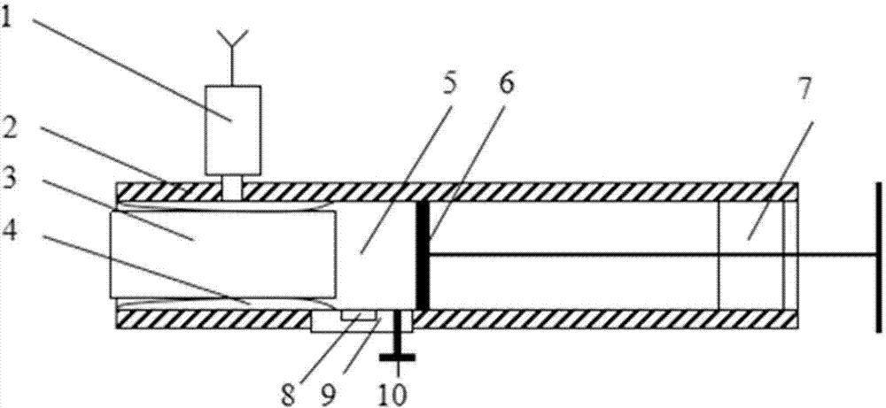
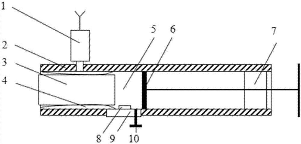
[0144] The core gas permeability measurement method, the measuring device used, and the calculation formula and derivation process of the core gas apparent permeability are the same as those in Example 1, except that the length of the core is 3.0cm; the hand-operated hydraulic pump works on the core. A confining pressure of 0.5MPa is applied; the piston moves at a constant speed of 0.1cm / s. Such as image 3 As shown, the pressure sensor in the portable core gas permeability measurement device protrudes from the inner wall of the cylinder. The cylinder is made of stainless steel, the cylinder length is 60cm, the cylinder wall thickness is 1.0cm, and the piston thickness is 3.5cm. The power source in the piston driving device is a battery, and the battery is placed in a power source slot embedded in the wall of the cylinder.

Embodiment 3

[0146] The core gas permeability measurement method, the measuring device used, and the calculation formula and derivation process of the core gas apparent permeability are the same as those in Example 1, except that the length of the core is 8.0cm; the hand hydraulic pump is used for the core A confining pressure of 3.0MPa is applied; the piston moves at a constant speed of 0.8cm / s. The cylinder is made of stainless steel, the cylinder length is 55cm, the cylinder wall thickness is 0.8cm, and the piston thickness is 4.0cm.


PUM

PropertyMeasurementUnit
thicknessaaaaaaaaaa
thicknessaaaaaaaaaa
lengthaaaaaaaaaa

Abstract

The invention discloses a measurement method of rock core gas logging permeability. The method comprises the following steps of inputting values of rock core diameter and length into a computing chip; putting a rack core into a rubber sleeve, and applying confining pressure by a small-sized hand-cranking hydraulic pump; pushing a piston to a minimum calibration position of an inner cavity, and closing an emptying valve; setting the moving speed of the piston, starting a piston driving device, stopping working when the piston is moved to a maximum calibration position of the inner cavity, calculating the apparent permeability of rock core gas by the computing chip, and further calculating the rock core gas logging permeability to complete first-time measurement; opening the emptying valve, and then closing the emptying valve after the pressure of the inner cavity is balanced; repeating the previous steps, moving the piston to the minimum calibration position of the inner cavity, and carrying out measurement for the second time; and calculating the average value of the twice measured values by the computing chip to obtain the final rock core gas logging permeability. According to the measurement method, the rock core gas logging permeability can be measured for two times in the back and forth movement process of the piston, so that the measurement method is high in measurement efficiency and high in measurement speed, and has an important significance for rapid evaluation of rock samples collected in the field.

Description

Technical field [0001] The invention belongs to the technical field of petroleum engineering, and relates to a core permeability measurement technology, in particular to a core gas permeability measurement method. Background technique [0002] In the petroleum industry, permeability is an important parameter that characterizes the ability of oil and gas to pass through reservoir rocks. Gas or liquid is usually used as a medium to measure core permeability. In indoor experiments, the test medium for gas permeability measurement can be helium or nitrogen. Air can also be used to measure rock permeability when the experimental accuracy is not high; the test medium for liquid permeability measurement is generally water or crude oil. [0003] Under normal circumstances, the laboratory core test results are relatively accurate, but the experimental equipment is large and requires high environmental requirements and is not convenient to carry in the field. In the field, portable rock samp...

Claims


Application Information

Patent Timeline
Patent Type & Authority Applications(China)
IPC IPC(8): G01N15/08
Inventor 申颍浩李曹雄葛洪魁
Owner CHINA UNIV OF PETROLEUM (BEIJING)
Learn More