Heat pump heat exchanger and heat pump using the same

A heat exchanger and heat pump technology, applied in the field of heat exchange, can solve the problems of uneven temperature, impact on the tube sheet, low heat exchange efficiency of the evaporative heat exchanger, etc., and achieve the effect of improving the heat exchange efficiency and prolonging the heat exchange path.

Active Publication Date: 2016-06-22
SHANDONG HONGLI HEAT PUMP ENERGY
View PDF6 Cites 0 Cited by
  • Summary
  • Abstract
  • Description
  • Claims
  • Application Information

AI Technical Summary

Problems solved by technology

However, in the manufacturing process of the existing heat exchanger, due to the limitation of the process size, the distance between the liquid supply pipe and the tube sheet is very short, causing the refrigerant liquid to directly hit the tube sheet after entering the evaporative heat exchanger, causing the refrigerant to churn and vortex and collide. generate large amounts of refrigerant foam
In this way, first, the refrigerant liquid enters the heat exchange tube bundle at an uneven flow rate, resulting in unequal temperature at each point in the heat exchanger, which reduces the energy efficiency ratio of the heat exchanger system; second, the refrigerant is divided into liquid parts, gas part and gas-liquid mixing part
Under these two conditions, the liquid part of the refrigerant is evaporated to obtain heat, the gas part will not evaporate again, and the gas-liquid mixed part has a very low evaporation due to flash evaporation, which eventually leads to the heat transfer efficiency of the evaporative heat exchanger being lower than the theoretical situation. very low, even as low as 50%
[0004] In addition, the refrigerant enters the heat exchange tube bundle at an uneven flow rate, and the temperature at each point in the heat exchange tube is uneven. During the evaporation process, it is easy to cause incomplete evaporation and the phenomenon of liquid droplets after evaporation.
The evaporated refrigerant enters the compressor with liquid droplets, which is not allowed by the operating conditions of the compressor and will cause damage to the compressor
[0005] When the existing heat exchanger is used as a condensing heat exchanger, the gas supply nozzle is directly aligned with the tube sheet of the heat exchange tube in the condensing heat exchanger, which will also cause the refrigerant gas to directly hit the tube after entering the condensing heat exchanger plate, causing the refrigerant to churn and vortex, causing the refrigerant gas to enter the heat exchange tube bundle at an uneven flow rate, causing the temperature at each point in the heat exchanger to be unequal, reducing the energy efficiency ratio of the heat exchanger system, and affecting the condensing heat exchanger heat transfer efficiency

Method used


Image

  • Heat pump heat exchanger and heat pump using the same
  • Heat pump heat exchanger and heat pump using the same
  • Heat pump heat exchanger and heat pump using the same

Examples


Embodiment Construction

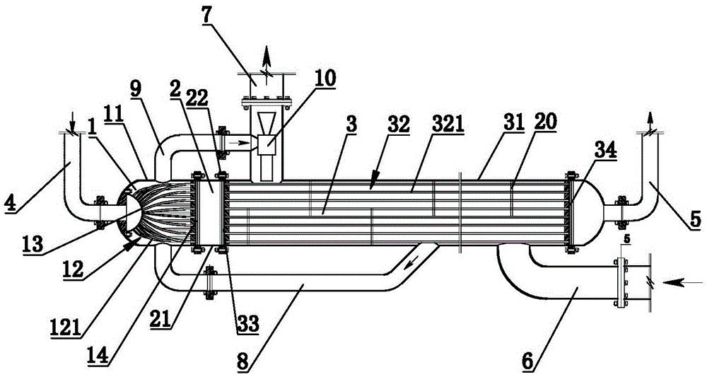
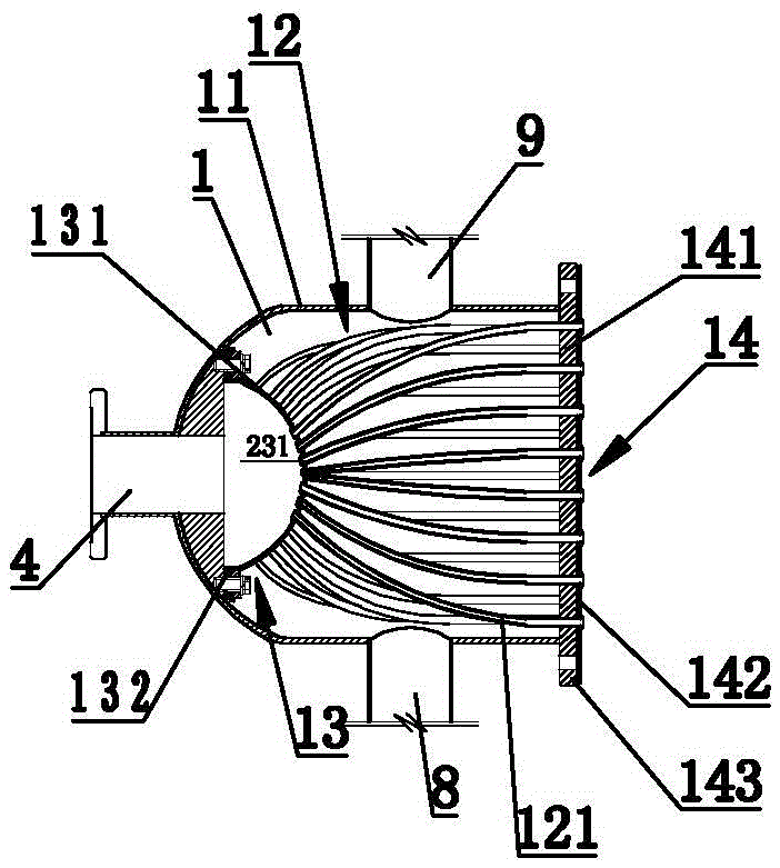
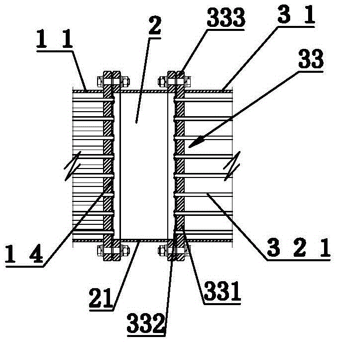
[0035] figure 1 is a structural schematic diagram of the heat pump heat exchanger of the present invention; figure 2 yes figure 1 Schematic diagram of the structure of the secondary heat exchange chamber; image 3 yes figure 1 Schematic diagram of the structure of the buffer tank in .

[0036] Refer to attached figure 1 , figure 2 as well as image 3 , a heat pump heat exchanger, including a secondary heat exchange compartment 1, a buffer compartment 2 and a main heat exchange compartment 3 connected in sequence.

[0037] Wherein, the main heat exchange cabin 3 includes a main heat exchange cabin shell 31, and a main heat exchange tube bundle 32 is arranged inside the main heat exchange cabin shell 31, and one end of the main heat exchange tube bundle 32 passes through a first main heat exchange tube plate 33 It communicates with the buffer compartment 2 , and the other end of the main heat exchange tube bundle 32 communicates with the refrigerant row pipe 5 through the...


PUM


Abstract

The invention discloses a heat pump heat exchanger, which comprises a secondary heat exchange cabin, a buffer cabin and a main heat exchange cabin which are connected in sequence; Heat pipe bundle, one end of the main heat exchange tube bundle communicates with the buffer compartment through the first main heat exchange tube plate, and the other end of the main heat exchange tube bundle communicates with the refrigerant exhaust pipe through the second main heat exchange tube plate; The cabin includes the shell of the auxiliary heat exchange cabin, and the auxiliary heat exchange cabin is provided with a capillary tube bundle, one end of the capillary tube bundle is connected with the refrigerant supply pipe through a capillary liquid separator, and the other end of the capillary tube bundle is connected with the buffer cabin through a capillary tube plate; The cabin includes a buffer cabin shell; the main heat exchange cabin is provided with a main water inlet pipe and a main water outlet pipe, and the auxiliary heat exchange chamber is provided with a water suction pipe connected to the main heat exchange chamber and an auxiliary water outlet pipe connected to the main water outlet pipe. The invention also discloses a heat pump using the heat exchanger. The pressure of the refrigerant in the main heat exchange tube of the present invention is balanced and the heat exchange efficiency is high.

Description

technical field [0001] The invention relates to the technical field of heat exchange, in particular to a heat pump heat exchanger and a heat pump using the heat exchanger. Background technique [0002] In the existing heat pump heat exchanger, the liquid (air supply) nozzle is directly aligned with the tube sheet of the heat exchange tube in the heat exchanger, and the heat exchange tube is connected through the tube sheet to perform evaporation or condensation. [0003] When the existing heat exchanger is used as an evaporative heat exchanger, the liquid supply nozzle is directly aligned with the tube sheet of the heat exchange tube in the evaporative heat exchanger, and the equivalent cross-sectional area of ​​the heat exchange tube bundle is generally larger than that of the liquid supply The cross-sectional area of ​​the tube. However, in the manufacturing process of the existing heat exchanger, due to the limitation of the process size, the distance between the liquid ...

Claims


Application Information

Patent Timeline
Patent Type & Authority Patents(China)
IPC IPC(8): F25B30/00F25B41/06F25B41/37
CPCF25B30/02F25B39/00F25B41/00F25B2400/052F25B2500/09F25B2339/00F25B41/37Y02P60/85
Inventor 于奎明
Owner SHANDONG HONGLI HEAT PUMP ENERGY
Why Eureka
Try Eureka