
Automatic preparation method of long-service-life cylinder-like crystal structural thermal barrier coating on surface of guide blade of hot end part of fuel machine

A technology of hot-end components and columnar crystals, which is applied in the field of long-life thermal barrier coating preparation, and can solve the problems of poor batch stability, low efficiency, and short service life of coatings

Active Publication Date: 2014-12-24
BEIJING GOLDEN WHEEL SPECIAL MACHINE
View PDF4 Cites 13 Cited by
  • Summary
  • Abstract
  • Description
  • Claims
  • Application Information

AI Technical Summary

Problems solved by technology

Gas turbine working blades are generally prepared by electron beam physical vapor deposition process. The coating has a columnar crystal structure, high strain tolerance, and long service life. The disadvantages are complex preparation process, expensive equipment, high preparation cost, low efficiency, and thin coating. The heat insulation performance is poor, and limited by the volume of the vacuum deposition chamber of the equipment, it is impossible to prepare coatings for large and complex surface components; the guide vanes and other stator components of gas turbines are generally prepared by plasma spraying technology, and the coating structure is a layered structure. Good thermal performance, simple equipment, low preparation cost, high spraying efficiency, but the disadvantages are poor bonding between coating layers, short service life, and the coating preparation method is also manual spraying, and the coating quality is poor in batch stability. Therefore, Conventional structural thermal barrier coatings have been difficult to meet the long-life requirements of ground gas turbines for tens of thousands of hours
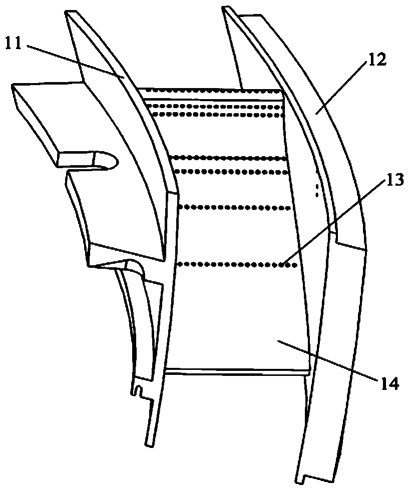
[0004] Drawing on the advantages of high strain tolerance of columnar crystal structure coatings and high heat insulation of layered structure coatings, the use of plasma spraying technology to prepare coatings with quasi-columnar crystal structure can greatly improve the service life of coatings. The research on the preparation process of the quasi-columnar crystal structure coating has been carried out on the sample. The domestic Beihang University has also carried out similar research. Process parameters such as substrate temperature, spraying trajectory, spraying power, powder feeding rate and spraying power matching have a significant impact on the formation of a columnar crystal structure coating, and a columnar crystal structure coating can be successfully prepared on a flat sample. The spraying process is not suitable for the hot-end parts of the gas turbine with complex profiles, especially for the guide vane. Because it is a multi-joint composite special-shaped structure, and the existing spraying methods are manual spraying, it is difficult to ensure accurate control of the spraying trajectory
Therefore, so far, the preparation of thermal barrier coatings with columnar crystal structure has been limited to the research on the surface of small flat samples in the laboratory, and has not been applied to the surface of gas turbine hot end components.

Method used


Image

  • Automatic preparation method of long-service-life cylinder-like crystal structural thermal barrier coating on surface of guide blade of hot end part of fuel machine
  • Automatic preparation method of long-service-life cylinder-like crystal structural thermal barrier coating on surface of guide blade of hot end part of fuel machine
  • Automatic preparation method of long-service-life cylinder-like crystal structural thermal barrier coating on surface of guide blade of hot end part of fuel machine

Examples


Embodiment Construction

[0025] The technical solution of the present invention will be described in further detail below in conjunction with the accompanying drawings and specific embodiments, but it is not intended as a limitation of the present invention

[0026] (1) Set the tool coordinate tool-HVOF according to the weight, center of gravity, and moment of inertia of the supersonic flame spray gun held by the manipulator, set the distance between the TCP point and the spray gun mouth as 330mm, the moving speed of the spray gun as 500m / s, and the distance between the spraying tracks as 20mm . According to the topography of the hot-end parts to be sprayed, the main program of supersonic flame spraying adhesive layer is compiled. The main program of spraying includes adhesive layer preparation preheating program and adhesive layer preparation program. Time count command.

[0027] (2) Compile the main program of the plasma spraying ceramic layer according to the topography of the hot-end parts to be ...


PUM


Abstract

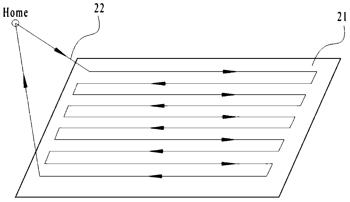
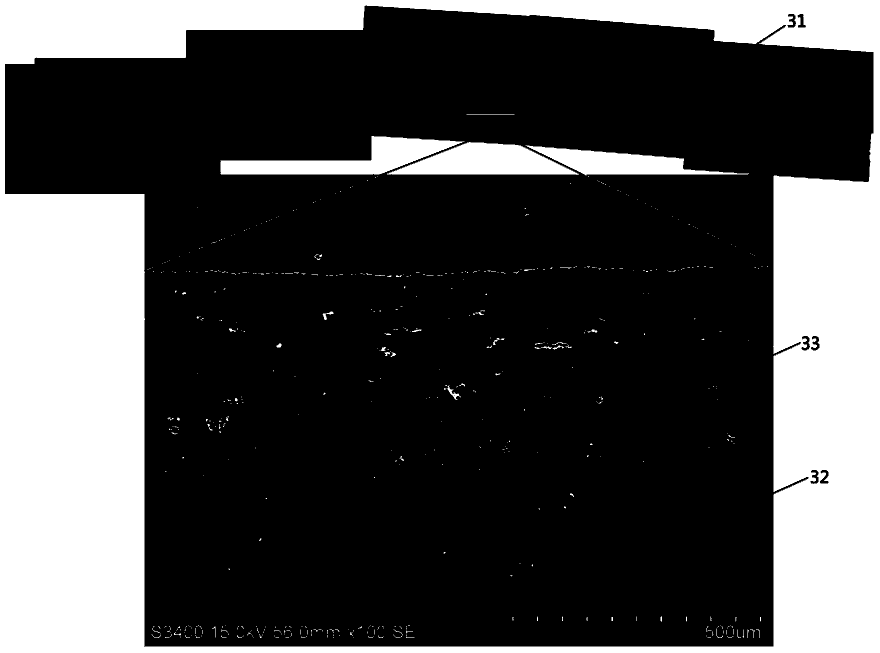
The invention relates to an automatic preparation method of a long-service-life cylinder-like crystal structural thermal barrier coating on the surface of a guide blade of a hot end part of a fuel machine. According to the invention, a supersonic flame spray gun and a plasma spray gun are respectively clamped by manipulators; an automatic spraying program is compiled; for a supersonic flame spraying bonding layer, by a main program, a distance from a TCP (Transmission Control Protocol) point to a spray gun orifice is set into 330 to 350mm, a moving speed of the spray gun is set into 500 to 600m / s and a spacing of spraying profiles is set into 20 to 30mm; for a plasma spraying ceramic layer, by the main program, a distance from the TCP point to a spray gun orifice is set into 60 to 70mm, a moving speed of the spray gun is set into 200 to 250m / s, a spacing of spraying profiles is set into 3 to 7mm; in the plasma spraying program compiling process, the trend of each spraying profile is of a shape of a Chinese character 'gong'. The automatic preparation method sequentially comprises the steps of preparation and pretreatment of a matrix, preparation of a bonding layer, preheating of the hot end part and preparation of a ceramic layer; a scanning electron microscope is adopted to observe; the prepared ceramic layer is of a cylinder-like crystal structure; strain tolerance and the thermal shock resistance service life of the coating are obviously improved; compared with the service life of the conventional structural thermal barrier coating, the service life of the coating is obviously prolonged.

Description

technical field [0001] The invention relates to a method for preparing a long-life thermal barrier coating, in particular to an automatic spraying method for preparing a long-life columnar crystal-like structure thermal barrier coating on the surface of a hot end part of a gas turbine. Background technique [0002] Due to the advantages of high efficiency, energy saving and low pollution, gas turbines have been widely used in aviation, ship power, power generation and other fields. In order to obtain higher energy efficiency and greater thrust, the inlet temperature of gas turbine turbines has gradually increased in recent years, and the improvement of material performance and structural design alone cannot meet the rapidly developing application requirements of gas turbines. Thermal barrier coatings have been successfully applied to the protection of aero-engines and heavy-duty gas turbine hot-end components due to their ability to effectively reduce the surface temperature...

Claims


Application Information

Patent Timeline
IPC IPC(8): C23C4/12C23C4/02C23C4/08C23C4/10C23C4/073C23C4/11C23C4/129C23C4/134
CPCY02T50/60
Inventor 汪瑞军傅斌友冉健袁涛
Owner BEIJING GOLDEN WHEEL SPECIAL MACHINE
Learn More