
A unitary ice storage air conditioning system

An ice-storage air-conditioning and unit-type technology is applied in the field of unit-type ice-storage air-conditioning systems, which can solve problems such as increasing the complexity of the system, reduce the volume of heat exchangers and transport energy consumption, reduce energy loss, and enhance internal disturbances. Effect

Inactive Publication Date: 2017-05-24
HENAN UNIV OF SCI & TECH
View PDF12 Cites 0 Cited by
  • Summary
  • Abstract
  • Description
  • Claims
  • Application Information

AI Technical Summary

Problems solved by technology

This method utilizes a vertical heat exchanger and air compressor, increasing the complexity of the system

Method used


Image

  • A unitary ice storage air conditioning system

Examples


Embodiment Construction

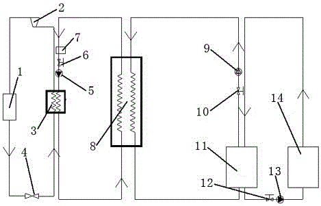
[0017] As shown in the figure, a unitary ice storage air conditioning system is composed of a refrigerant circulation circuit, a refrigerant circulation circuit, an ice making circuit and a refrigeration circuit;

[0018] The refrigerant circulation circuit is a circulation circuit formed by sequentially connecting the fan 1, the throttle valve 4, the heat exchanger 3 and the compressor 2, wherein the refrigerant enters the heat exchanger 3 after being throttled by the throttle valve 4 Absorb the heat released by the brine in the brine circulation loop to raise the temperature, then compress in the compressor 2 and be cooled by the fan 1 to complete the cycle;

[0019] The refrigerant circulation circuit is a circulation circuit formed by connecting the refrigerant storage tank 7, the control valve I6, the centrifugal pump I5, the heat exchanger 3 and the subcooler 8 in sequence, wherein the refrigerant is formed by the refrigerant storage tank 7, and after passing through the...


PUM


Abstract

The invention relates to a unit-type ice storage air conditioning system which comprises a refrigerant circulation loop, a secondary refrigerant circulation loop, an ice making loop and a refrigerating loop, wherein the refrigerant circulation loop is formed by sequentially connecting a fan, a throttling valve, a heat exchanger and a compressor; the secondary refrigerant circulation loop is formed by sequentially connecting a secondary refrigerant storage box, a control valve I, a centrifugal pump I, a heat exchanger and a subcooler; the ice making loop is formed by sequentially connecting an ice storage bucket, a control valve II, a gas-liquid mixing pump and the subcooler; the refrigerating loop is formed by sequentially connecting the ice storage bucket, a control valve III, a centrifugal pump II and the tail end of an air conditioner. The unit-type ice storage air conditioning system utilizes an ice making system to make and store ice at a low ebb of power utilization at night and utilizes stored ice slurry to carry out refrigerating and cooling at the peak of power utilization so as to take effects of carrying out peak load shifting and avoiding the peak of power utilization; the ice slurry is thawed and adsorbs heat at the tail end of the air conditioner at the user side and has a great quantity of latent heat of phase change and heat exchange temperature difference of the air at the tail end of the air conditioner and the ice slurry is high, so that the size and transport energy consumption of the heat exchanger can be effectively reduced; generated low-temperature supplied air has good heat comfort.

Description

technical field [0001] The invention relates to the field of industrial refrigeration, in particular to a unitary ice storage air conditioning system. Background technique [0002] Ice slurry is a solid-liquid two-phase mixed solution containing a large number of tiny ice crystal particles, which has good fluidity and great phase change potential. As a high-quality refrigerant, ice slurry has a huge application space in the fields of HVAC, refrigeration and refrigeration. Nowadays, there are many ways to make ice slurry, among which the supercooling method has the advantages of simple system, high ice production rate, small energy loss, low initial investment, etc., and has broad application prospects. In order to improve the ice-making efficiency and prevent ice blockage in the subcooler, the inner tube and outer tube of the supercooled water continuous production device disclosed in the application numbers 201220028410.3 and 201210020121.3 are made of conductive materials...

Claims


Application Information

Patent Timeline
Patent Type & Authority Patents(China)
IPC IPC(8): F24F5/00
Inventor 梁坤峰任岘乐贾雪迎袁争印
Owner HENAN UNIV OF SCI & TECH
Learn More