
Velocity model constructing and calculating method for ground monitoring microseism location

A velocity model, micro-seismic technology, applied in seismic signal processing and other directions, can solve the problems of occupying well resources, high production costs, affecting positioning accuracy, and harsh monitoring conditions.

Inactive Publication Date: 2014-12-10
UNIV OF ELECTRONICS SCI & TECH OF CHINA
View PDF3 Cites 21 Cited by
  • Summary
  • Abstract
  • Description
  • Claims
  • Application Information

AI Technical Summary

Problems solved by technology

[0004] The in-well monitoring method requires that there must be a monitoring well near the fracturing well. At the same time, this method occupies well resources and the production cost is relatively high. In addition, it also requires the spatial and lateral resolution of the observation instrument, so the monitoring conditions are relatively harsh in specific implementation.
Although ground monitoring also has disadvantages such as being greatly affected by environmental noise and the location of observation points affecting positioning accuracy, with the development of signal processing technology and the improvement of ground geophone performance, the positioning accuracy of ground monitoring microseismic is also continuously improving. Ground monitoring Fracturing microseismic positioning will take advantage of its low-cost advantage to become a future development trend

Method used


Image

  • Velocity model constructing and calculating method for ground monitoring microseism location
  • Velocity model constructing and calculating method for ground monitoring microseism location
  • Velocity model constructing and calculating method for ground monitoring microseism location

Examples


Embodiment Construction

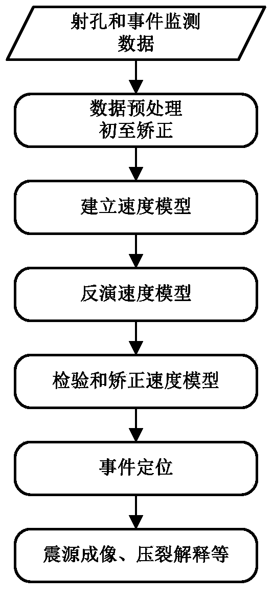
[0042] The present invention provides a velocity model construction and solution method for ground monitoring and microseismic positioning, which mainly involves the S1 establishment, S2 solution and S3 correction process of the necessary velocity model from the data preprocessing process to the event positioning process. The following is the present invention detailed technical plan.

[0043] The S1: the establishment of the velocity model includes the following steps:

[0044] S11: Construction of the velocity model of the ground monitoring microseismic work area;

[0045] Considering the actual situation of the ground monitoring seismic positioning work area, we believe that the velocity propagation in the work area is mainly affected by the anisotropy of the formation, which mainly comes from: the effect of stress field, the effect of directional alignment of fractures, and the generation of fractures and thin interbeds. combination effect.

[0046]Since there are many s...


PUM


Abstract

The invention discloses a velocity model constructing and calculating method for ground monitoring microseism location, wherein the model is constructed based on a geophysical microseism linearization location method and an anisotropic average velocity model, in order to achieve construction and optimization solution of the three-dimensional anisotropic average velocity model, in comparison with the traditional laminated velocity model, the velocity model is closer to the actual simulation formation velocity so as to achieve a simple and reasonable calculating process, at the same time, through the velocity model constructing and calculating method, the laminated velocity model error caused due to ray tracing differentiation is also prevented; through the method, a residual vector between observation time and calculated travel-time difference of an appointed detector within a work area range and the optimization solution model are constructed, the least square solution of the velocity model can be obtained by iterating the model and inverted into the optimal velocity model, and crack events can be precisely located through the velocity model.

Description

technical field [0001] The invention belongs to the field of microseismic monitoring, and in particular relates to a velocity model for ground monitoring microseismic positioning. Background technique [0002] Microseismic monitoring and positioning technology is a new technology emerging from the geothermal development industry. Since the technology was proposed in the 1970s, microseismic monitoring technology has been widely applied to dynamic monitoring of oil and gas reservoirs, dynamic monitoring of coal fields, and dynamic monitoring of geothermal engineering. And many other aspects, and achieved good application results. At present, in the process of unconventional oil and gas development, fracturing measures are mainly used to increase the production of oil fields. The fracturing measures have a very obvious effect on increasing the production of low-permeability oil fields and carbonate oil fields. Due to the underground rock fracture caused by fracturing activitie...

Claims


Application Information

Patent Timeline
IPC IPC(8): G01V1/28
Inventor 费高雷魏会东胡光岷
Owner UNIV OF ELECTRONICS SCI & TECH OF CHINA
Learn More