
Wafer testing machine stand

A wafer testing and machine technology, which is applied in semiconductor/solid state device testing/measurement, electrical components, circuits, etc. The effect of reducing time, reducing costs and reducing emergencies

Inactive Publication Date: 2014-12-03
INNOVATIVE TURNKEY SOLUTION
View PDF7 Cites 2 Cited by
  • Summary
  • Abstract
  • Description
  • Claims
  • Application Information

AI Technical Summary

Problems solved by technology

[0005] However, when inspecting hundreds of dies, the probes on the wafer testing machine are usually kept fixed, and the wafer below is used to rotate and move, so it is easy to cause poor stability during wafer testing. There are many emergencies, which will increase the cost and the cost of testing equipment; in addition, when setting the test, it will also take more time to set up the equipment

Method used


Image

  • Wafer testing machine stand
  • Wafer testing machine stand
  • Wafer testing machine stand

Examples


Embodiment Construction

[0014] In order to make the purpose, technical features and advantages of the present invention better understood by those skilled in the art and to implement the present invention, the technical features and implementation methods of the present invention are explained in the following description in conjunction with the accompanying drawings, and Preferred embodiments are listed for further description, but the following descriptions of the embodiments are not intended to limit the present invention, and the accompanying drawings below are schematic representations related to the characteristics of the present invention.

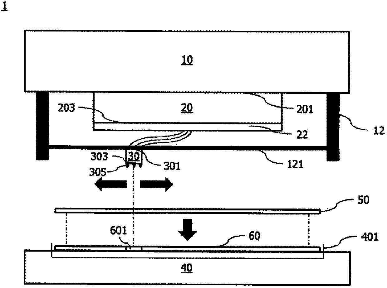
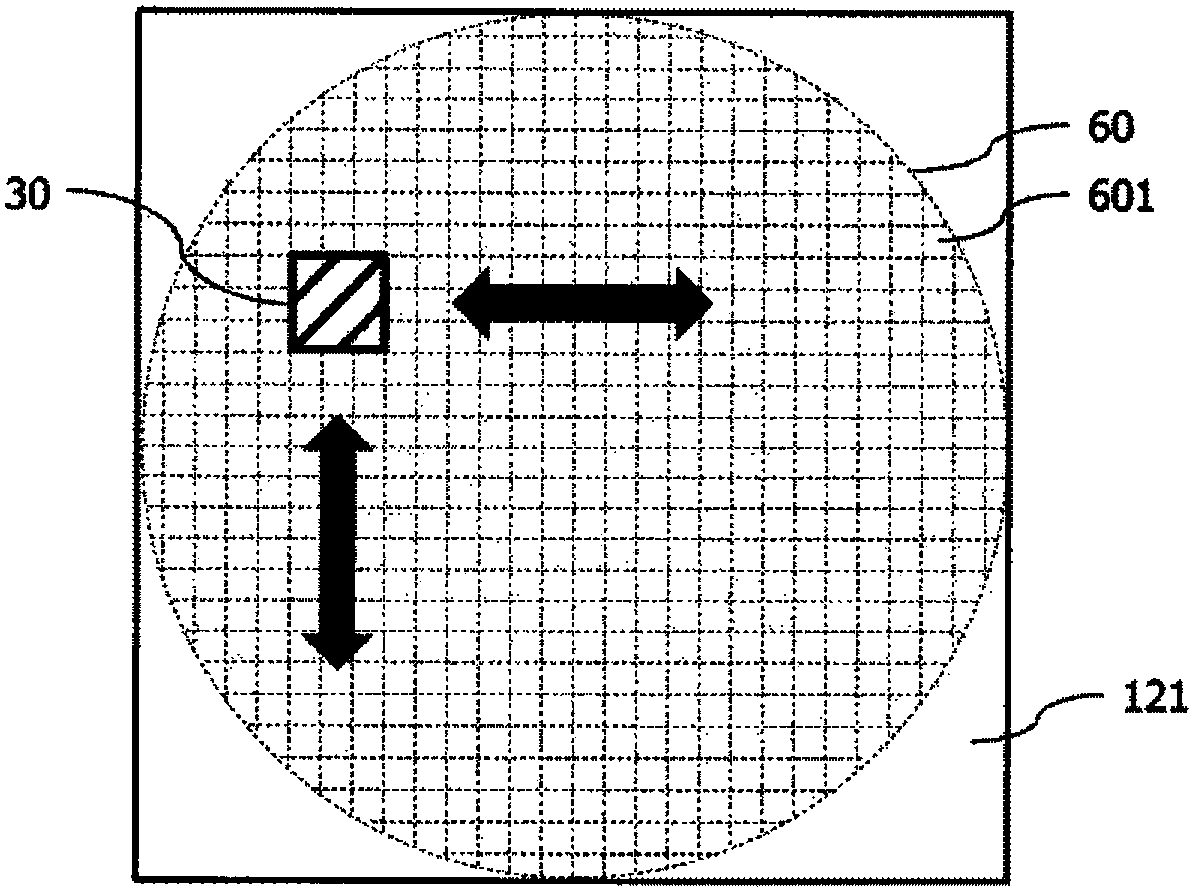
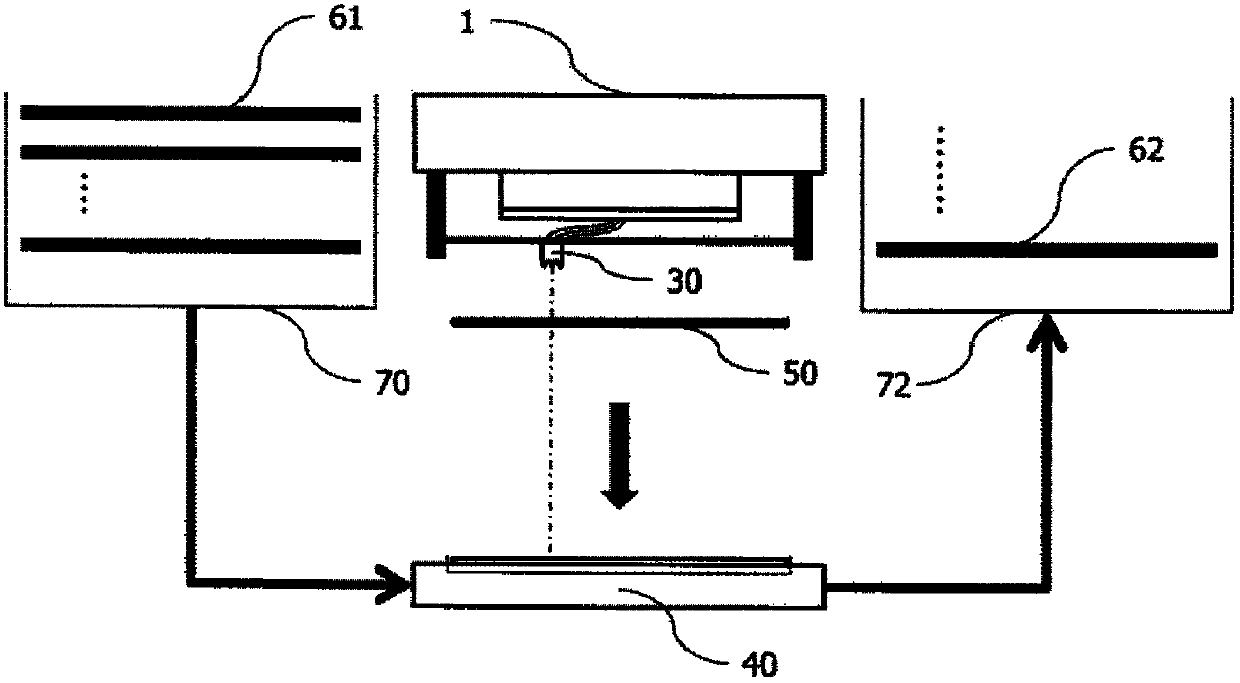
[0015] see figure 1 , is a cross-sectional view of the wafer testing machine of the present invention. Such as figure 1 As shown, the wafer testing machine 1 includes: a test head 10 electrically connected to the outside world; a probe tower 20 having an upper surface 201 and a lower surface 203 opposite to the upper surface 201, wherein the upper surface...


PUM


Abstract

The invention provides a wafer testing machine stand. Crystal grains on a wafer can be detected via movement of a probe base without rotating movement of the wafer so that detection can be performed more stably and rapidly, possible emergent situations can be reduced, cost and expense of testing machines and tools can be reduced and time for setting the machines and the tools can also be reduced.

Description

technical field [0001] The present invention relates to a wafer testing machine, in particular to a wafer testing machine for fast and stable testing of crystal grains. Background technique [0002] In the semiconductor process, wafer processing (Waferfabrication) is the most capital-intensive and technology-intensive part, and the upstream industry accompanying wafer processing includes product design (ICdesign), wafer manufacturing (Wafermanufacture), and mask (Photomask) ) manufacturing, etc., the downstream industry includes IC packaging (Packaging), testing (Testing), packaging (Assembly) generally known as semiconductor back-end processes (Back-end processes), and peripheral lead frame manufacturing (Lead-frame manufacture), connection Connectormanufacture, boardmanufacture, etc. This closely integrated industrial system has formed the lifeline of Taiwan's economy today. [0003] Each process usually includes several inspection steps to detect the status of the curren...

Claims


Application Information

Patent Timeline
IPC IPC(8): H01L21/66
CPCH01L22/20H01L22/14
Inventor 陈石矶
Owner INNOVATIVE TURNKEY SOLUTION
Learn More