
Temperature and stress measuring device based on orthogonal dual-polarization fiber laser

A technology of fiber laser and fiber laser, which is applied to measuring devices, thermometers with physical/chemical changes, thermometers, etc., can solve the problems of reducing demodulation accuracy, increasing cost and complexity, and achieving mature, simple and stable manufacturing processes Good, high-sensitivity effect

Inactive Publication Date: 2014-12-03
TIANJIN UNIV
View PDF8 Cites 7 Cited by
  • Summary
  • Abstract
  • Description
  • Claims
  • Application Information

AI Technical Summary

Problems solved by technology

Although the optical fiber sensing technology mentioned above can achieve temperature-strain dual-parameter differential measurement, it is inevitable to use some complex optical fiber sensing head processing technologies in the production process, such as chemical corrosion, mechanical polishing, and sensor head coating. Overlay process
At the same time, in the demodulation process, at least one set of equipment is often required to realize the demodulation output, and it involves analyzing the output data of different types of signals (such as wavelength, beat frequency, etc.), which greatly reduces the demodulation accuracy and improves the system performance. cost and complexity

Method used


Image

  • Temperature and stress measuring device based on orthogonal dual-polarization fiber laser
  • Temperature and stress measuring device based on orthogonal dual-polarization fiber laser
  • Temperature and stress measuring device based on orthogonal dual-polarization fiber laser

Examples


Embodiment Construction

[0012] The present invention will be further described below in conjunction with the accompanying drawings.

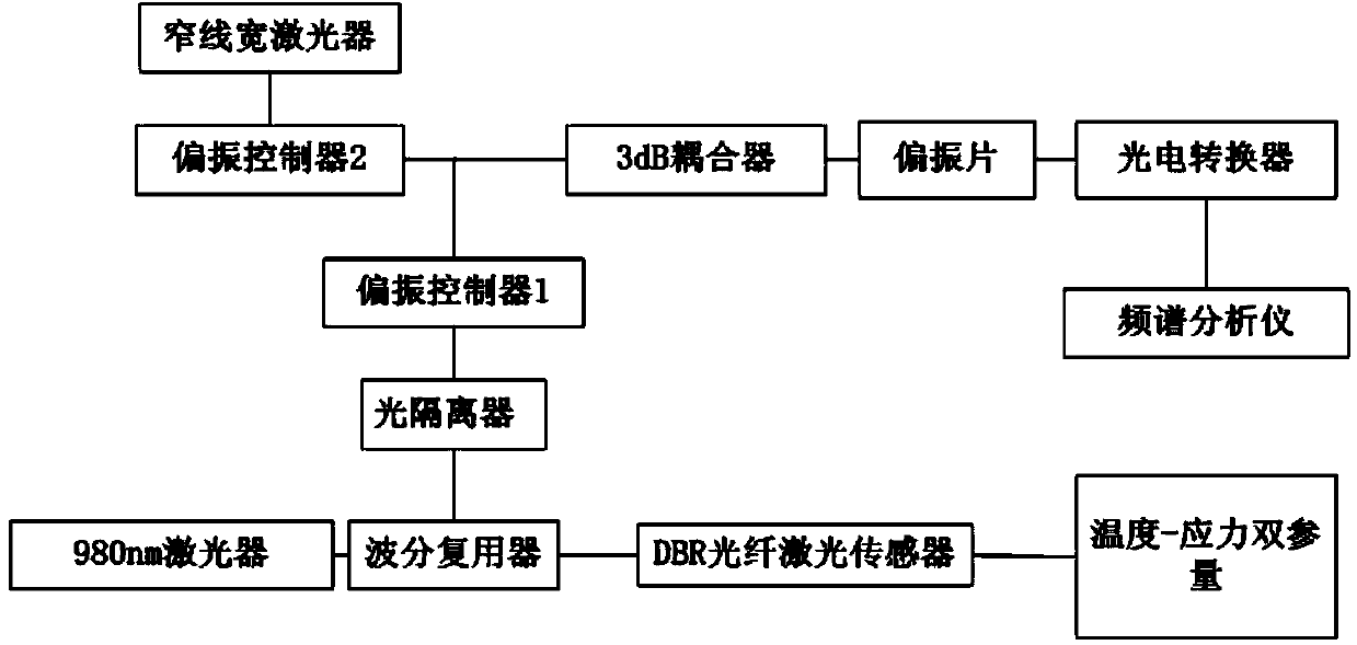
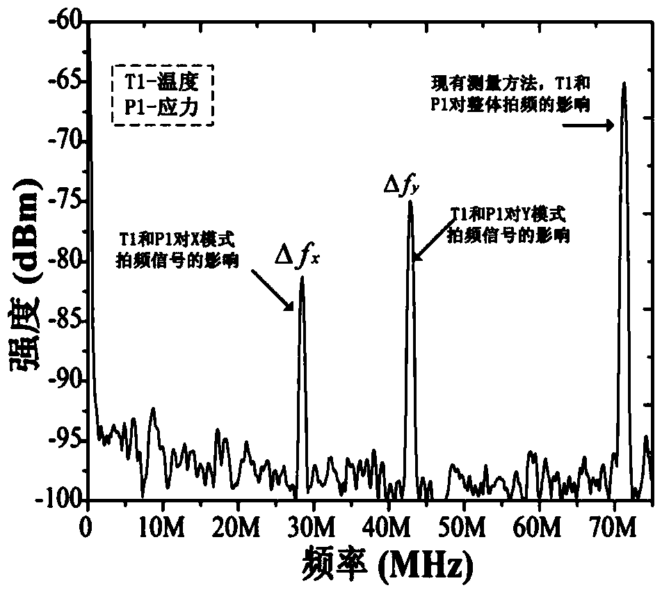
[0013] The invention includes three parts: an optical fiber sensing unit, a signal processing unit and a signal demodulation unit. The optical fiber sensing unit is a single longitudinal mode dual polarization DBR fiber laser sensor; the signal processing unit includes a 980nm laser, a 980 / 1550 nm wavelength division multiplexer, an optical isolator, a polarization controller, a narrow linewidth laser, and 3dB A coupler, a polarizer and a photoelectric converter; the signal demodulation unit is a spectrum analyzer. The sensing unit is a DBR (Distributed Bragg Reflection) fiber laser, which is composed of a pair of FBG gratings and a resonant cavity. See figure 1 . Since the pair of FBG sub-gratings have the same temperature sensitivity and different stress sensitivity, the two groups of gratings have the same temperature sensitivity under the action of external tempe...


PUM


Abstract

The invention relates to a temperature and stress measuring device based on an orthogonal dual-polarization fiber laser, and the measuring device is used for detecting stress and temperature signals. The measuring device comprises a DBR fiber laser sensor, a wavelength division multiplexer, a 980nm laser, a narrow-line-width laser, a 3dB coupler, a photoelectric converter, two polarization controllers and a frequency spectrum analyzer, wherein the DBR fiber laser sensor outputs laser signals whose wavelength is about the waveband 1550nm; laser generated by the 980nm laser is input to the DBR fiber laser sensor through the wavelength division multiplexer; both temperature and stress signals act on the DBR fiber laser sensor; optical signals, which are generated via energy conversion by the DBR fiber laser sensor and include temperature and stress modulation information to be measured, are returned to the wavelength division multiplexer and then isolated and output by an optical isolator; and energy of energy-adjustable narrow-line-width laser signals output by the narrow-line-width laser is adjusted by the second polarization controller, and the narrow-line-width laser signals as well as two groups orthogonal polarization optical signals, which are output by the first polarization controller after adjustment and include temperature and stress modulation information to be measured, are input to the 3dB coupler. Thus, the temperature and stress measuring device can detect temperature and stress signals at the same time.

Description

Technical field [0001] The invention belongs to the field of optical fiber sensing, and in particular relates to a sensing device capable of simultaneously detecting temperature signals and stress signals based on orthogonal double-polarized fiber lasers. Background technique [0002] In the field of practical application of optical fiber sensing technology, temperature and stress are two very important physical parameters in sensing and detection. Especially in the field of safety monitoring and process control of large bridges, tunnels, dams, etc., the two basic physical parameters of temperature and stress must be monitored. However, since most of the optical fibers themselves are sensitive to temperature and stress at the same time, it is often impossible to clearly separate the specific effects of the two, which severely restricts the application of optical fiber sensing technology in the temperature-stress dual-parameter differential measurement to a certain extent. d...

Claims


Application Information

Patent Timeline
Patent Type & Authority Applications(China)
IPC IPC(8): G01K11/32G01L1/24G01K11/3206
Inventor 吕辰刚高靖宜王晗郭玺任畅李本萍
Owner TIANJIN UNIV
Learn More