Art spraying device and spraying process thereof

A sprayer, art technology, applied in the field of art sprayer and its spraying process, can solve the problems of inconvenient cleaning, inconvenience, complex structure, etc., to improve speed and uniformity, good social and economic benefits, and reasonable design. Effect

Inactive Publication Date: 2014-12-03
NORTH CHINA UNIV OF WATER RESOURCES & ELECTRIC POWER
View PDF4 Cites 3 Cited by
  • Summary
  • Abstract
  • Description
  • Claims
  • Application Information

AI Technical Summary

Problems solved by technology

However, the uneven water distribution and absorption in this way of smearing will eventually affect the final shape of the three-dimensional brush characters
When drawing traditional Chinese painting with a brush, it is also necessary to partially or mostly wet the drawing paper before painting. It is not easy to grasp the strength of the brush and the amount of water dipped in the painting directly, and it is impossible to realize the control of the painting process. Optimal control, affecting the shaping of the final work
When drawing some traditional Chinese paintings or writing brush characters, it is necessary to color the bottom layer of the drawing paper. The traditional method is to spray directly with a watering can. This method cannot control the coloring pattern and spraying area, and often causes a large area of ​​​​infinite coloring, which affects writing. The cleanliness of the countertop is inconvenient to clean
There are also some finished inkjet works without professional tools and mechanical assistance. Traditional spraying machinery is extremely inconvenient to use, with cumbersome processes and complex structures, which cannot meet market demand.
[0003] Therefore, to produce a kind of art sprayer and its spraying process with simple structure, convenient operation, wide application range, simple process, high operation and work efficiency, which can fill the vacancy of painting professional spraying tools in the market

Method used


Image

  • Art spraying device and spraying process thereof
  • Art spraying device and spraying process thereof
  • Art spraying device and spraying process thereof

Examples


Embodiment 1

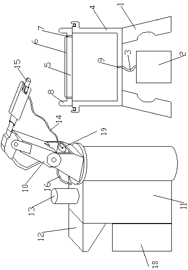
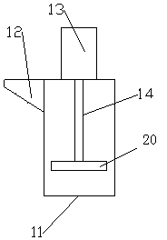
[0016] Embodiment 1: as figure 1 , 2 , shown in 3, a kind of art sprayer, comprises support 1, and described support 1 is fixedly installed with receiving trough 4, and the top of receiving trough 4 is movably installed with support plate 5, and is movably installed above support plate 5 There is a work surface 6, and the support plates 5 on both sides of the work surface 6 are provided with leakage holes 7, the leakage holes 7 communicate with the material receiving tank 4, and the bottom of the material receiving tank 4 is provided with a discharge port 9, and the material discharge The bottom of the port 9 is provided with a material receiving hose 3, and the lower part of the material receiving hose 3 is provided with a material receiving cylinder 2, and a mechanical arm 10 is fixedly installed above one side of the material receiving tank 4, and one side of the mechanical arm 10 is fixedly installed. There is a batching bucket 11, a stirring motor 13 is arranged above th...

Embodiment 2

[0019] Embodiment 2: as figure 1 , 2, shown in 3, a kind of art sprayer, comprises support 1, and described support 1 is fixedly installed with receiving trough 4, and the top of receiving trough 4 is movably installed with support plate 5, and is movably installed above support plate 5 There is a work surface 6, and the support plates 5 on both sides of the work surface 6 are provided with leakage holes 7, the leakage holes 7 communicate with the material receiving tank 4, and the bottom of the material receiving tank 4 is provided with a discharge port 9, and the material discharge The bottom of the port 9 is provided with a material receiving hose 3, and the lower part of the material receiving hose 3 is provided with a material receiving cylinder 2, and a mechanical arm 10 is fixedly installed above one side of the material receiving tank 4, and one side of the mechanical arm 10 is fixedly installed. There is a batching bucket 11, a stirring motor 13 is arranged above the...

Embodiment 3

[0022] Embodiment 3: as figure 1 , 2 , shown in 3, a kind of art sprayer, comprises support 1, and described support 1 is fixedly installed with receiving trough 4, and the top of receiving trough 4 is movably installed with support plate 5, and is movably installed above support plate 5 There is a work surface 6, and the support plates 5 on both sides of the work surface 6 are provided with leakage holes 7, the leakage holes 7 communicate with the material receiving tank 4, and the bottom of the material receiving tank 4 is provided with a discharge port 9, and the material discharge The bottom of the port 9 is provided with a material receiving hose 3, and the lower part of the material receiving hose 3 is provided with a material receiving cylinder 2, and a mechanical arm 10 is fixedly installed above one side of the material receiving tank 4, and one side of the mechanical arm 10 is fixedly installed. There is a batching bucket 11, a stirring motor 13 is arranged above th...


PUM


Abstract

The invention relates to an art spraying device and a spraying process thereof. A receiving groove is fixedly formed in a support, and support plates are movably mounted on the receiving groove; leaking holes are formed in the support plates on the two sides of a working table and communicated with the receiving groove; a flexible receiving pipe is arranged at the bottom of a discharge opening, and a receiving barrel is movably arranged below the flexible receiving pipe. A burdening barrel is fixedly mounted on one side of a mechanical arm, and a stirring motor is arranged above the burdening barrel; a stirring shaft is connected below the stirring motor, and a stirring disc is fixedly mounted at the bottom of the stirring shaft; a controller is arranged on one side of the mixing barrel and connected with the mechanical arm and a water suction pump mounted on the mechanical arm through conducting wires; one side of the water suction pump is communicated with the burdening barrel through a first connecting pipe, and the other side of the water suction pump is connected with a nozzle mounted at the tail end of the mechanical arm through a second connecting pipe. The art spraying device can efficiently and quickly carry out water mist spraying and can also spray pigment and mixed pigment at the same time.

Description

technical field [0001] The invention relates to the art field, in particular to an art painting auxiliary equipment and process, in particular to an art sprayer and its spraying process. Background technique [0002] There are many kinds of art paintings, and when drawing art works, whether it is traditional Chinese painting or oil painting, spraying technology often appears. The traditional painting process is not equipped with a special spraying machine to assist in completing the spraying operation. When writing three-dimensional brush characters, since the writing of three-dimensional brush characters requires a large amount of water to assist, it is necessary to soak the drawing paper first, so that the ink can diffuse into the drawing paper along with the water. The traditional method is to use a brush directly dipped in water, and then apply layer by layer on the drawing paper until the drawing paper is completely covered. However, the water distribution and absorpt...

Claims


Application Information

Patent Timeline
Patent Type & Authority Applications(China)
IPC IPC(8): B44C1/20B05B9/04B05B15/04
Inventor 魏东宋可陈岩吴华堂孙亚婷
Owner NORTH CHINA UNIV OF WATER RESOURCES & ELECTRIC POWER
Why Eureka
Try Eureka