
Invertor-surge resistant insulated wire

一种绝缘电线、变频器的技术,应用在绝缘电缆、绝缘体、绝缘导体等方向,达到局部放电起始电压高、绝缘性能及耐热老化特性优异的效果

Active Publication Date: 2014-11-26
ESSEX FURUKAWA MAGNET WIRE LLC
View PDF9 Cites 11 Cited by
  • Summary
  • Abstract
  • Description
  • Claims
  • Application Information

AI Technical Summary

Problems solved by technology

However, even the insulated wires described in Patent Documents 1 and 2 have room for further improvement in partial discharge inception voltage, insulation performance at high temperature, and thermal aging resistance.

Method used


Image

  • Invertor-surge resistant insulated wire
  • Invertor-surge resistant insulated wire
  • Invertor-surge resistant insulated wire

Examples


Embodiment 1

[0113] A flat conductor (copper with an oxygen content of 15 ppm) having a chamfering radius of r=0.3 mm at the four corners was prepared in a size of 1.8×3.4 mm (thickness×width). When forming the enamelled layer, use a mold similar to the shape of the conductor to apply polyamide-imide resin (PAI) varnish (manufactured by Hitachi Chemical, trade name: HI406, relative dielectric constant ε1: 3.9) to the conductor. , and at a speed of 15 seconds for the sintering time, it passed through a sintering furnace with a furnace length of 8 m set at 450° C., and a varnish layer with a thickness of 5 μm was formed by this 1st sintering process. By repeating this process, an enameled layer with a thickness of 25 μm was formed, and an enameled wire with a film thickness of 25 μm was obtained.

[0114] The obtained enameled wire was used as a core wire, and the screw of the extruder used 30 mm full flight, L / D=20, and compression ratio 3. Polyetheretherketone (PEEK) (manufactured by SOLV...

Embodiment 2~4 and comparative example 3 and 4

[0116] Except for changing the thicknesses of the enameled layer and the extrusion-coated resin layer to those shown in Tables 2 to 4, insulated wires made of PEEK extrusion-coated enameled wires were obtained in the same manner as in Example 1. . Table 2 shows the minimum value of the tensile modulus of each extrusion coating resin layer at 25° C. to 250° C. and the degree of crystallinity obtained by the above measurement method. Extrusion temperature conditions were performed according to Table 1.

Embodiment 5

[0118] As the enamelling resin, polyimide resin (PI) varnish (manufactured by Unitika, trade name: U Imide, relative dielectric constant ε1: 3.5) was used instead of polyamideimide, and the enamelled layer and extrusion coating Except having changed the thickness of the resin layer to the thickness shown in Table 2, it carried out similarly to Example 1, and obtained the insulated electric wire which consists of PEEK extrusion-coated enameled wire. Table 2 shows the minimum value of the tensile modulus of the extrusion coating resin layer at 25° C. to 250° C. and the degree of crystallinity obtained by the above measurement method. Extrusion temperature conditions according to Table 1.


PUM

PropertyMeasurementUnit
tensile modulusaaaaaaaaaa
relative permittivityaaaaaaaaaa
tensile modulusaaaaaaaaaa

Abstract

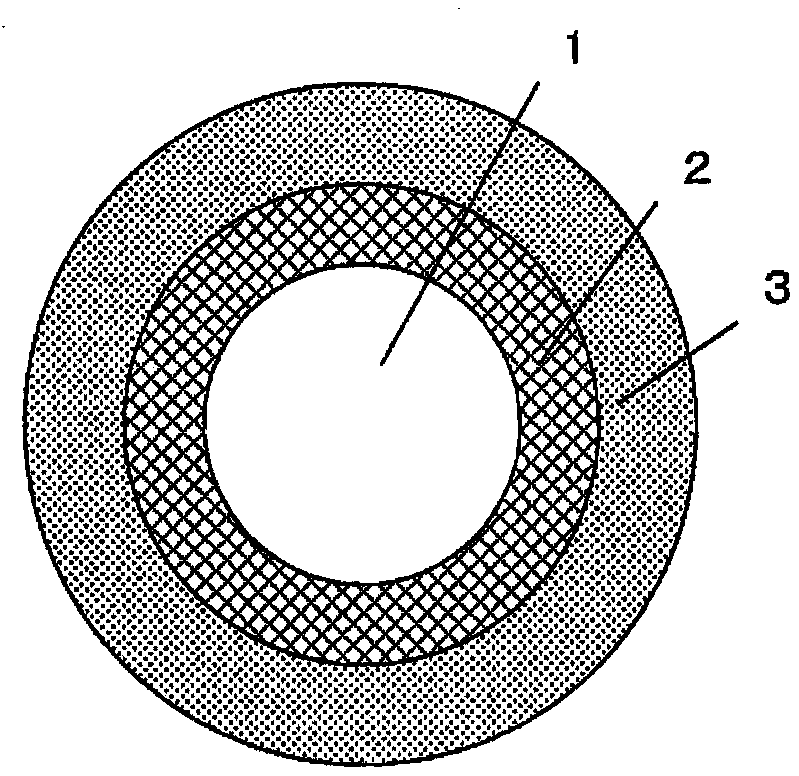
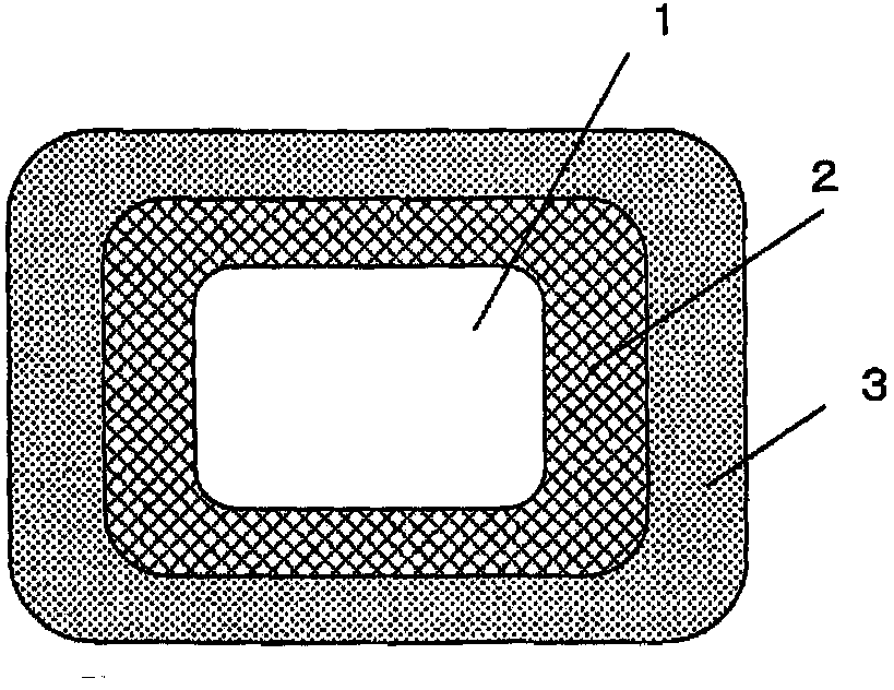
An invertor-surge resistant insulated wire provided with at least one layer of an enamel fusion layer (2) on the outer circumference of a conductor (1), and at least one layer of an extrusion-coating resin layer (3) on the outer side of the enamel fusion layer (2). The combined thickness of the enamel fusion layer (2) and the extrusion-coating resin layer (3) is equal to or greater than 50μm, the thickness of the enamel fusion layer (2) is equal to or less than 60μm, and the thickness of the extrusion-coating resin layer (3) is equal to or less than 200μm. The minimum tensile elasticity of the extrusion-coating resin layer (3) at 25-250ºC is equal to or greater than 100MPa. The relative dielectric constant of an insulating layer, which is a combination of the enamel fusion layer (2) and the extrusion-coating resin layer (3), is equal to or less than 3.5 at 25 ºC, and equal to or less than 5.0 at 250 ºC. The relationship between the relative dielectric constant (ε1') of the enamel fusion layer (2) at 250 ºC and the relative dielectric constant (ε2') of the extrusion-coating resin layer (3) at 250 ºC satisfies (ε2' / ε1')>1.

Description

technical field [0001] The invention relates to an anti-frequency converter surge insulated wire. Background technique [0002] Frequency converters (inverters) are installed on many electrical equipment as effective variable speed control devices. Inverters perform switching at several kHz to tens of kHz, and surge voltages are generated in response to these pulses. Inverter surge (inverter surge) is a phenomenon in which reflection occurs at a discontinuous point of impedance within its transmission system, such as the beginning or end of the connected wiring, and as a result, a maximum output voltage of the inverter is applied. 2 times the voltage. In particular, the output pulses generated by high-speed conversion elements such as IGBTs have a high voltage steepness, so even if the connecting cable is shortened, the surge voltage is high, and the voltage attenuation caused by the connecting cable is also small. The output voltage is nearly 2 times the voltage. [000...

Claims


Application Information

Patent Timeline
Patent Type & Authority Applications(China)
IPC IPC(8): H01B7/02H02K3/30
CPCH02K3/30Y02T10/641H01B7/02H01B13/065H01B3/307H01B3/427H01B3/42H01B7/0216H01B7/08Y02T10/64H01B7/0283
Inventor 武藤大介福田秀雄富泽惠一仲聪志
Owner ESSEX FURUKAWA MAGNET WIRE LLC
Learn More