
Cone beam CT scatter correction method and device based on complementary gratings

A scattering correction and grating technology, which is applied in the fields of medical imaging and industrial non-destructive testing, can solve problems such as limitations and difficulties in achieving satisfactory results, and achieve the effects of improving quality, reducing adverse effects, and good convenience

Active Publication Date: 2014-11-26
NORTHWESTERN POLYTECHNICAL UNIV
View PDF10 Cites 17 Cited by
  • Summary
  • Abstract
  • Description
  • Claims
  • Application Information

AI Technical Summary

Problems solved by technology

In cone-beam CT, due to the use of an area array detector, the scattering is distributed in two dimensions, and it is difficult to achieve satisfactory results with a single hardware correction or software correction method. Therefore, a hybrid correction method combining hardware and software has emerged, such as Beam- Stop Array, Beam-Hole Array, beam attenuation grid, fixed beam blocking bar, moving beam blocking bar, attenuation plate imaging method, primary ray modulation correction method, etc.
Although these methods have achieved a certain effect of scatter correction, for the high-quality and strong adaptive cone-beam CT imaging that is increasingly emphasized, these methods usually have many approximations and assumptions, and are often subject to many restrictions in practical applications. limit

Method used


Image

  • Cone beam CT scatter correction method and device based on complementary gratings
  • Cone beam CT scatter correction method and device based on complementary gratings
  • Cone beam CT scatter correction method and device based on complementary gratings

Examples


Embodiment Construction

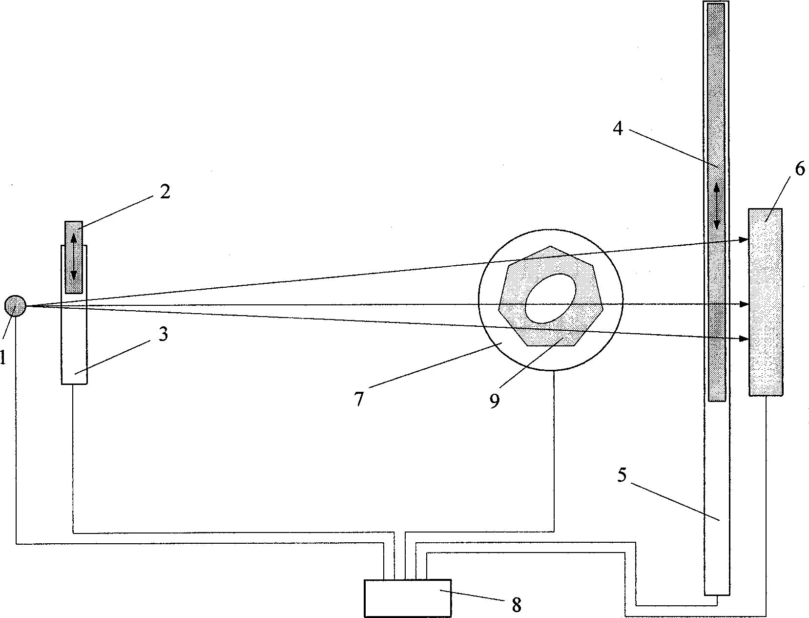
[0045] refer to figure 1 The scatter correction device for cone-beam CT of the present invention includes: a ray source 1, an area array detector 6, a scanning mechanism 7, a front complementary grating 2 and its translation mechanism 3, a rear complementary grating 4 and its translation mechanism 5, system control and Computer 8 for calculation, wherein the front complementary grating 2 and the rear complementary grating 4 can be equipped at the same time, or only one of them can be equipped. The measured object 9 is placed on the scanning mechanism 7 .

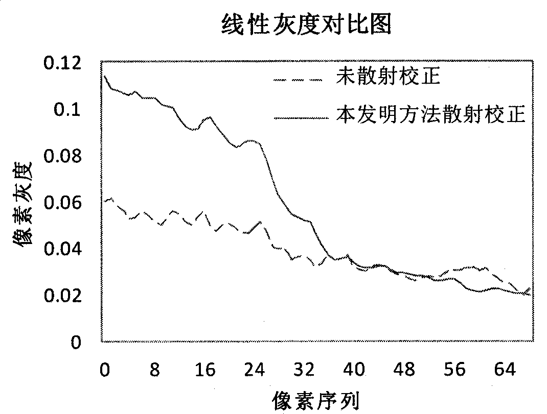
[0046] On a cone beam CT constructed according to the present invention (the X-ray source is Y.TU450-D02 of YXLON, the flat panel detector is PaxScan2520 of Varian, and possesses scanning mechanism, pre-complementary grating and translation mechanism thereof, post-complementary grating and its translation mechanism, system control and calculation computer), apply the method of the present invention to an iron part to carry ...


PUM


Abstract

The invention discloses a cone beam CT scatter correction method and device based on complementary gratings. The scatter correction of projected images is achieved through simple and reliable complementary grating scanning and a small amount of calculation, and scatter correction slice images can be rebuilt out through the projected images obtained after scatter correction is finished. The cone beam CT scatter correction method and device based on the complementary gratings are suitable for tested objects of any complexities, the method is good in accuracy, reliability, stability and convenience, adverse effects on cone beam CT images from scattering are reduced to the maximum extent, and therefore the quality of the cone beam CT slice images is improved obviously.

Description

technical field [0001] The invention belongs to the fields of medical imaging and industrial non-destructive testing related to the application of cone-beam CT, and relates to a cone-beam CT scattering correction method and a device thereof based on complementary gratings. Background technique [0002] Cone Beam Computed Tomography (CBCT), as an advanced medical imaging and industrial non-destructive testing technology, is playing an increasingly important role in real life. It obtains a series of projection data of the measured object at different angles through the X-ray source and the area array detector, and then uses the corresponding reconstruction algorithm to obtain continuous slice images. Compared with traditional two-dimensional CT, cone beam CT has the advantages of fast scanning speed, continuous slice sequence, high image resolution, and high utilization rate of rays. [0003] Scattering effect is an important factor affecting image quality during CT imaging. ...

Claims


Application Information

Patent Timeline
IPC IPC(8): A61B6/03G01N23/04
Inventor 黄魁东张定华张华徐哲
Owner NORTHWESTERN POLYTECHNICAL UNIV
Learn More