
Combustion device with heat exchange function

A technology of combustion equipment and combustion chamber, which is applied in the direction of lighting and heating equipment, burners, combustion methods, etc., which can solve the problems of short circuit of heat storage body, reduced heat exchange efficiency, and easy occurrence of bias flow, etc., so as to suppress the formation of nitrogen oxides , Improve heat exchange efficiency and slow down the effect of local high temperature zone

Inactive Publication Date: 2014-11-19
中冶华天南京工业炉有限公司
View PDF6 Cites 1 Cited by
  • Summary
  • Abstract
  • Description
  • Claims
  • Application Information

AI Technical Summary

Problems solved by technology

On the one hand, air and gas are distributed unevenly after entering the regenerator in the combustion equipment, and the airflow naturally flows in the direction of the channel with less resistance, which eventually causes the airflow in the regenerator to be biased
As we all know, the bias flow phenomenon in the heat storage body will reduce the heat transfer efficiency of the peripheral parts of the heat storage body, while the middle part with less resistance will cause the heat storage body to "overburn" due to excessive temperature, and finally show the effective circulation of the heat storage body Reduced area, reduced actual thermal efficiency, shortened service life, high furnace pressure and other unfavorable conditions; There is an installation seam of 8-10 mm on the upper wall surface of the hot box, but when the combustion is reversed and the smoke is reversed, the flue gas will naturally flow to the installation seam with less resistance, and the waste heat of the flue gas will be discharged without being absorbed by the heat storage body , the exhaust gas temperature is too high, the heat transfer efficiency of the regenerator is greatly reduced, that is, the "short circuit" phenomenon of the regenerator; moreover, the traditional guide brick adopts a single nozzle or double nozzle structure, which makes the air and gas mix unevenly during combustion , Insufficient combustion, poor temperature uniformity, and prone to bias flow

Method used

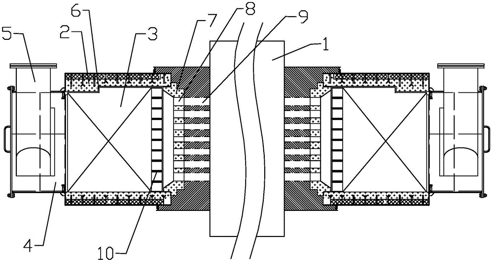
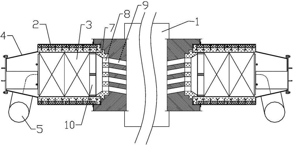
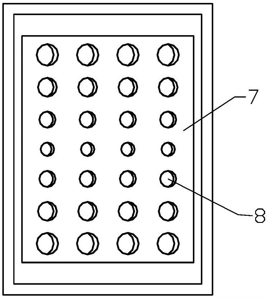

Image

  • Combustion device with heat exchange function
  • Combustion device with heat exchange function
  • Combustion device with heat exchange function

Examples


Embodiment 1

[0020] Such as Figure 1-2 As shown, the heat exchange combustion equipment described in the embodiment of the present invention at least includes a combustion chamber 1 and a heat storage device communicated with the combustion chamber. Such as Figure 1-2 As shown in , it can be divided into the first heat storage device on the left and the second heat storage device on the right. Wherein, the structures of the first heat storage device and the second heat storage device are the same. First of all, it needs to be introduced that the heat storage device includes a heat storage box 2 with a heat storage body 3 inside, one end surface of the heat storage box communicates with the interior of the combustion chamber through an array hole structure, and the heat storage box The other end face communicates with a drainage cavity 4; a flow diverter is provided in the drainage cavity; the drainage cavity 4 communicates with a gas connection pipe 5; the upper edge surface of the inn...


PUM


Abstract

The invention discloses a combustion device with the heat exchange function. The combustion device with the heat exchange function at least comprises a combustion chamber and a heat storage device which is communicated with the combustion chamber, wherein a heat storage device comprises a heat storage box, a heat storage body is arranged inside the heat storage box, one end face of the heat storage box is communicated with the interior of the combustion chamber through an array hole structure, the other end face of the heat storage box is communicated with a drainage cavity, a drainage device is arranged in the drainage cavity, the drainage cavity is communicated with an air pipe, the surface of the upper edge of the inner wall of the heat storage box is of a step structure in the direction of airflow, and the upper surface of the heat storage body is matched with the surface of the upper edge of the inner wall of the heat storage box, and a gap is reserved between the upper surface of the heat storage body and the surface of the upper edge of the inner wall of the heat storage box. According to the combustion device with the heat exchange function, air or gas is divided into multiple fluid regions through a drainage plate structure and is led into the heat storage body, and the phenomenon that airflow deviates due to the fact that on-way resistances to the airflow in the heat storage body are different is avoided; due to the fact that the step structure is arranged on the surface of the upper edge of the inner wall of the heat storage box, the phenomenon that overburning occurs due to excessively-high local temperature, caused by short circuits of smoke, of the heat storage body is avoided during reversing combustion; due to the fact that guiding bricks with array holes are adopted, air and gas are mixed more evenly, and combustion can be more complete.

Description

technical field [0001] The invention relates to the technical field of high-efficiency combustion application in industrial furnace pits, in particular to heat exchange combustion equipment. Background technique [0002] At present, due to domestic metallurgy, chemical industry, cement and other industries' increasing requirements for the output of single industrial furnaces, the heating capacity and equipment volume of individual combustion equipment are also increasing day by day. On the one hand, air and gas are distributed unevenly after entering the regenerator in the combustion equipment, and the airflow naturally flows in the direction of the channel with less resistance, which eventually causes the airflow in the regenerator to be biased. As we all know, the bias flow phenomenon in the heat storage body will reduce the heat transfer efficiency of the peripheral parts of the heat storage body, while the middle part with less resistance will cause the heat storage body...

Claims


Application Information

Patent Timeline
Patent Type & Authority Applications(China)
IPC IPC(8): F23D14/66
CPCY02E20/34
Inventor 王浩曹强周炜
Owner 中冶华天南京工业炉有限公司
Learn More