
Passive containment cooling system

A passive containment and cooling system technology, applied in cooling devices, nuclear power generation, reactors, etc., can solve the problems of not considering the heat exchange between the inner shell and the outside, affecting the safety of nuclear power plants, and low heat exchange efficiency. Achieve the effects of reducing the effective circulation area, improving the heat export effect, and improving the heat exchange efficiency

Pending Publication Date: 2021-03-09
CHINA NUCLEAR POWER ENG CO LTD
View PDF5 Cites 0 Cited by
  • Summary
  • Abstract
  • Description
  • Claims
  • Application Information

AI Technical Summary

Problems solved by technology

Among them, the outer shell and inner shell of EPR are both 1.3m prestressed reinforced concrete, the outer shell of WWER is 0.6m reinforced concrete structure, the inner shell is 1.2m prestressed reinforced concrete, and the outer shell structure of ACP1000 is reinforced concrete. The inner shell is made of prestressed reinforced concrete with a steel lining on the inside. In these three types of reactors with double-layer containment, the main function of the outer shell is to prevent impact, and the inner shell is used to bear pressure. However, this type of double containment reactor The layered containment reactor type does not consider the problem of heat exchange between the inner shell and the outer shell
There are also some double-layer containment reactor types that can export heat from the inner shell, such as the AP600 and AP1000 series in the United States, and the CAP1400 reactor type in China. The inner shell is used as the boundary of heat exchange, and the containment is taken away by evaporation in the early stage. In the later stage, air convection is used to take away the heat in the containment, so that the temperature and pressure in the containment are kept below the design value, which ensures the integrity of the containment. Types are used to provide air circulation channels, which have problems such as low heat transfer efficiency and poor earthquake resistance, which affect the safety of nuclear power plants, and the economy is poor

Method used


Image

  • Passive containment cooling system
  • Passive containment cooling system
  • Passive containment cooling system

Examples


Embodiment 1

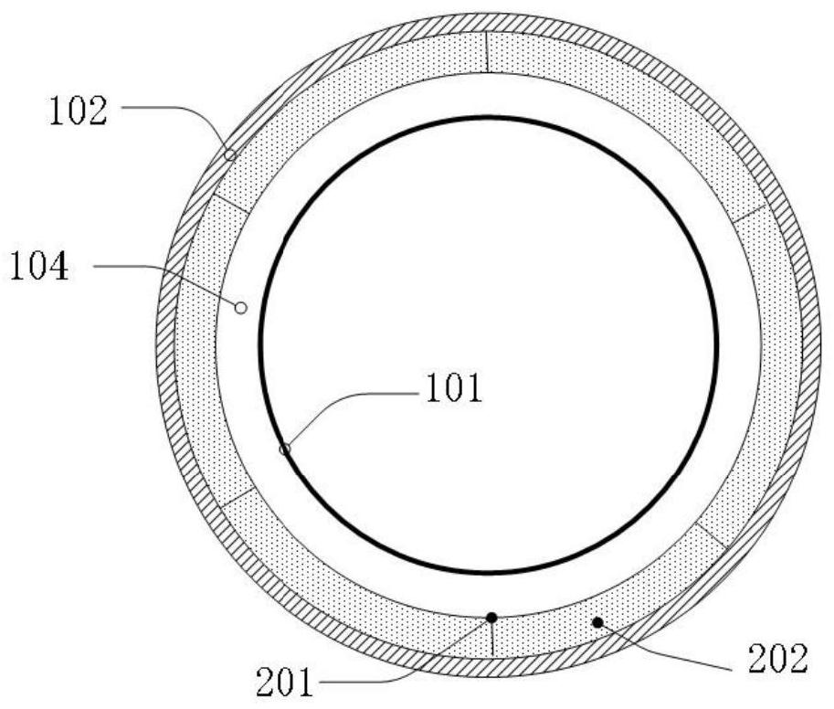
[0038] like figure 1 , figure 2 As shown, this embodiment provides a passive containment cooling system, including: including a containment 101 , a shielding case 102 , and a configuration device 103 .

[0039] Wherein, the shielding shell 102 surrounds the containment shell 101 to protect the containment shell 101, and a certain distance is kept between the shielding shell 102 and the containment shell 102, so that an air flow channel 104 is formed between them. The shielding case 102 is provided with an air inlet 105 and an air outlet 106, and the air passage 104 communicates with the external atmosphere through the air inlet 105 and the air outlet 106 respectively, so that the air in the atmosphere can freely enter into the air passage 104 and from The air channel 104 is discharged, and the air exchanges heat with the wall surface of the containment vessel when the air flows through the wall surface of the containment vessel 101 in the air channel 104, so that the heat in...


PUM


Abstract

The invention provides a passive containment cooling system, which comprises a containment, a shielding shell and a configuration device, the shielding shell surrounds the containment, an air flow channel is formed between the containment and the shielding shell, the shielding shell is provided with an air inlet and an air outlet, the air flow channel is communicated with the external atmosphericenvironment through the air inlet and the air outlet; the configuration device is arranged on the inner side of the shielding shell, distributed in the circumferential direction of the shielding shelland used for controlling the area of the air flow channel. According to the passive containment cooling system, the heat exchange efficiency and the anti-seismic property can be improved, and the safety of a nuclear power plant can be improved.

Description

technical field [0001] The invention belongs to the field of nuclear technology, and in particular relates to a passive containment cooling system. Background technique [0002] As the third layer of shielding structure for radioactive materials in nuclear power plants, containment can contain radioactive materials in the containment. Therefore, it is very important to ensure the integrity of the containment. [0003] At present, there are various forms of protection for the integrity of the containment in third-generation nuclear power plants, among which the main reactor types (eg, EPR, WWER, ACP1000, AP600, and AP1000) all adopt the double-layer containment design. Among them, the outer shell and inner shell of EPR are both 1.3m prestressed reinforced concrete, the outer shell of WWER is 0.6m reinforced concrete structure, the inner shell is 1.2m prestressed reinforced concrete, and the outer shell structure of ACP1000 is reinforced concrete. The inner shell is made of p...

Claims


Application Information

Patent Timeline
Patent Type & Authority Applications(China)
IPC IPC(8): G21C15/18G21C15/253
CPCG21C15/18G21C15/253Y02E30/30
Inventor 于明锐韩旭李云屹元一单刘卓王洪亮冯雨贾凝晰
Owner CHINA NUCLEAR POWER ENG CO LTD
Learn More