
Welded joint of intercommunicating liquid-cooled rack and manufacturing method thereof

A technology for welding joints and liquid cooling racks, applied in welding equipment, welding equipment, auxiliary welding equipment, etc., can solve the problem of low welding qualification rate of rack or chassis, remelting of cold plate brazing seam, and limited welding space and other problems, to achieve the effect of simple structure, good welding seam sealing and high qualification rate

Active Publication Date: 2016-03-02
CHENGDU SIWI HIGH TECH IND GARDEN
View PDF6 Cites 0 Cited by
  • Summary
  • Abstract
  • Description
  • Claims
  • Application Information

AI Technical Summary

Problems solved by technology

The step-by-step welding method of the chassis or rack can greatly improve the welding qualification rate compared with the traditional overall brazing, but due to the large heat input when welding the fillet welds, it is easy to cause remelting and loss of the cold plate brazing seams
In addition, due to structural limitations, part of the welding space is limited, and at the same time, due to the influence of solder remelting, welding defects are also prone to occur during fusion welding, resulting in a low welding pass rate of the entire rack or chassis

Method used


Image

  • Welded joint of intercommunicating liquid-cooled rack and manufacturing method thereof
  • Welded joint of intercommunicating liquid-cooled rack and manufacturing method thereof
  • Welded joint of intercommunicating liquid-cooled rack and manufacturing method thereof

Examples


Embodiment Construction

[0033] The present invention will be further described below in conjunction with the accompanying drawings, but the protection scope of the present invention is not limited to the following description.

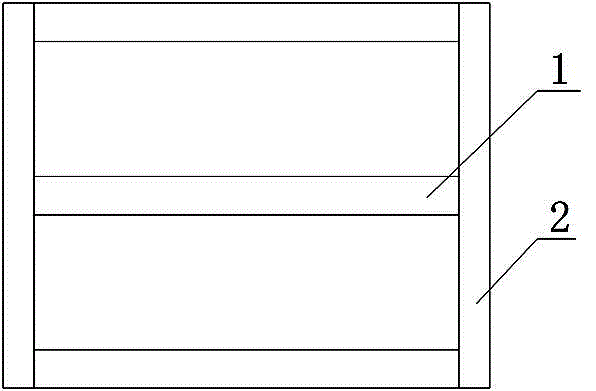
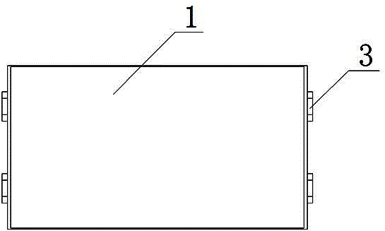
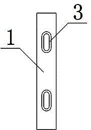
[0034] Such as figure 1 As shown, a welded joint of an intercommunicating liquid-cooled rack includes a welding cold plate 1 and a connecting cold plate 2, such as figure 2 As shown, the two sides of the welding cold plate 1 are respectively provided with at least two tenons 3, such as image 3 As shown, tenon 3 is a hollow structure, such as Figure 4 and Figure 5 As shown, the connecting cold plate 2 is provided with a vertically downward groove 4, and the bottom of the groove 4 is provided with a plurality of mortises 5 consistent with the number of the welded cold plate 1. 3 are matched, and there is a cover plate groove 6 along the side wall of the groove 4, and a cold plate cover plate is installed in the cover plate groove 6; the welded cold plate 1 is horizontall...


PUM


Abstract

The invention relates to an intercommunication liquid-cooled rack welding joint. The welding joint comprises a welding cold plate (1) and connecting cold plates (2), and two or more tenons (3) are arranged on the two sides of the welding cold plate (1) respectively. Vertically downward grooves (4) are formed in the connecting cold plates (2), and multiple tenon grooves (5) are formed in the bottoms of the grooves (4). The appearance size of the tenon grooves (5) is matched with that of the tenons (3), a cover plate groove (6) is further formed in the upper portion of the side wall of each groove (4), and a cold cover plate is assembled in each cover plate groove (6). The welding cold plate (1) is horizontally installed between the two connecting cold plates (2). A manufacturing method includes the steps that S1, the welding cold plate (1) is manufactured; S2, the connecting cold plates (2) are manufactured; S3, the tenons (3) and the tenon grooves (5) are assembled and welded; S4, the cover plates are assembled and welded; S5, air tightness is detected. The intercommunication liquid-cooled rack welding joint has the advantages of being simple in structure, good in weld seam seal performance, convenient to repair and high in structural strength.

Description

technical field [0001] The invention relates to a liquid-cooled heat dissipation structure, in particular to a welded joint of intercommunicating liquid-cooled racks and a manufacturing method thereof. Background technique [0002] The rapid development of electronic technology makes it possible to assemble electronic equipment with high frequency, high power and high density, which makes the power consumption of electronic equipment continue to increase within a limited volume range, and the heat flux density rises sharply, resulting in a rapid increase in the temperature of electrical components of the equipment , causing more and more failures of electronic equipment. According to the survey, 55% of electronic equipment failures are caused by overheating, and overheating damage has become the main failure mode of electronic equipment. In order to meet the increasingly high heat dissipation requirements, modern racks or cabinets have generally adopted liquid cooling struc...

Claims


Application Information

Patent Timeline
Patent Type & Authority Patents(China)
IPC IPC(8): B23K33/00B23K15/00B23K37/00
CPCB23K31/02B23K33/00B23K37/00
Inventor 王远荣敬小军马兰刘雁斌
Owner CHENGDU SIWI HIGH TECH IND GARDEN
Learn More