A flue gas waste heat recovery and cascade utilization system

A flue gas waste heat and cascading technology, which is applied in waste heat treatment, lighting and heating equipment, furnace components, etc., can solve the problems that the system can only provide hot water and the power consumption of water pumps is high, so as to save heating costs and meet energy needs , Reduce the effect of initial investment

Active Publication Date: 2017-11-28
鹤壁盾安供热有限公司
View PDF2 Cites 0 Cited by
  • Summary
  • Abstract
  • Description
  • Claims
  • Application Information

AI Technical Summary

Problems solved by technology

At present, the technology that has been applied is to use the method of direct heat exchange between water and flue gas for waste heat recovery, such as Chinese patent ZL201010266231.9, but since the heat exchange equipment is basically carried out under normal pressure, the temperature of the produced water is at 70°C around, and the system can only provide hot water
Another example is Chinese patent ZL200820069478.X which discloses an organic Rankine cycle system, which can be used to recover waste heat from heating furnaces to generate electricity, but the system can only provide one form of electric energy
Therefore, if any one of the above-mentioned patent methods is used alone, the initial investment of the heat exchanger, the circulating water flow required for heat exchange, and the power consumption cost of the water pump are all very large.

Method used


Image

  • A flue gas waste heat recovery and cascade utilization system

Examples


Embodiment Construction

[0019] Below in conjunction with accompanying drawing and specific embodiment the present invention is described in further detail:

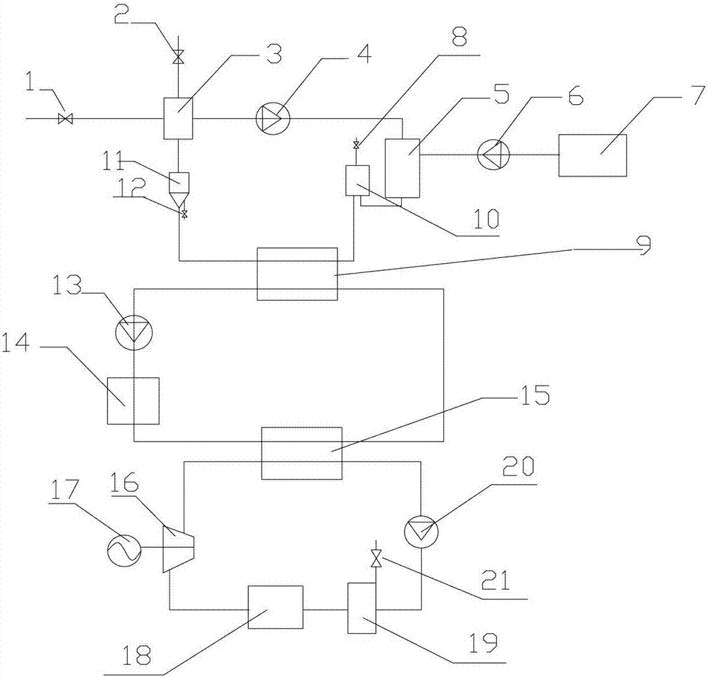
[0020] The flue gas waste heat recovery device of the present invention directly exchanges heat between the source water and the flue gas and then enters the primary water independent circulation, and the water in the waste heat circulating water heating device enters the secondary water independent circulation after indirect heat exchange with the primary heat exchanger, so that The carbon dioxide liquid in the waste heat power generation device enters three independent cycles after indirect heat exchange with the secondary heat exchanger.

[0021] Such as figure 1 As shown, the flue gas waste heat recovery and cascade utilization system of the present invention includes: a flue gas waste heat recovery device, a waste heat circulating water heating device, a waste heat power generation device and connecting pipes, the flue gas waste heat recove...


PUM


Abstract

The invention discloses a smoke afterheat recovery and gradient utilization system. The smoke afterheat recovery and gradient utilization system comprises a smoke afterheat recovery device, an afterheat circulating water heating device, an afterheat generation device and a connecting pipe, wherein the first-stage heat exchange is performed between the smoke afterheat recovery device and the afterheat circulating water heating device by a primary heat exchanger; and the second-stage heat exchange is performed between the afterheat circulating water heating device and the afterheat generation device by a secondary heat exchanger. The smoke afterheat recovery and gradient utilization system has the following benefits: the industrial waste gas afterheat is fully used, so that the independent heating cost is reduced, and the environmental pollution is relieved. Under the precondition of not changing the heat exchange quantity, the return water temperature of secondary water is reduced through the carbon dioxide circulation, the temperature difference from the primary heat exchanger is increased, the combined heat and power supply is realized, the various energy demands of a factory are satisfied, and the heat exchange area of the primary heat exchanger can be effectively decreased, so that the initial investment of the heat exchangers is reduced, the circulating water flow needed by the heat exchange is decreased, the power consumption of a water pump is reduced, and the gradient utilization of energy is realized.

Description

technical field [0001] The invention relates to a utilization of waste heat of flue gas, in particular to a system for waste recovery of flue gas and thermal cascade heat / electricity utilization produced by on-line alumina production in aluminum metallurgy industry. Background technique [0002] At present, in the alumina production process, saving energy and reducing consumption is an effective means to reduce production costs and improve economic benefits. Many relevant institutions have done a lot of research on energy-saving technologies and processes. Among them, the waste heat recovery of flue gas at about 150 °C in alumina roasting furnaces is an important link. Reasonable utilization of waste heat after recovery can improve heat utilization efficiency. At present, the technology that has been applied is to use the method of direct heat exchange between water and flue gas for waste heat recovery, such as Chinese patent ZL201010266231.9, but since the heat exchange equ...

Claims


Application Information

Patent Timeline
Patent Type & Authority Patents(China)
IPC IPC(8): F27D17/00
CPCY02P10/25
Inventor 蔡景辉马静罗丹
Owner 鹤壁盾安供热有限公司
Why Eureka
Try Eureka