
Pump-type discharge container

A container and pump type technology, applied in the direction of spraying device, liquid spraying device, packaging, etc., can solve the problems of accidental liquid leakage, liquid leakage, slight movement of the nozzle head up and down, etc., to achieve the effect of reducing resistance

Active Publication Date: 2014-10-15
DAIWA CAN
View PDF6 Cites 7 Cited by
  • Summary
  • Abstract
  • Description
  • Claims
  • Application Information

AI Technical Summary

Problems solved by technology

[0005] Such a pump-type spray container is usually designed such that when the nozzle head is pressed down, the second check valve for opening and closing the outlet of the liquid chamber opens immediately as the piston linked with the nozzle head descends, Therefore, if the nozzle head is pushed down even slightly, the second check valve at the outlet of the liquid chamber will open, and as a result, the liquid in the liquid chamber will leak to the outside.
For example, even if it is a pump-type discharge container provided with a top cover and a stopper so that the nozzle head does not fall from the upper limit position, if the container packed in the carton is transported in an upside-down state by mistake, the The nozzle head may move up and down slightly due to vibrations caused by unevenness of the road surface, etc.
At this time, when the container is turned upside down by mistake, the first check valve composed of a ball valve or the like will open under the action of gravity, thus causing the liquid in the container body to enter the liquid chamber.
Moreover, there is such a problem: the nozzle head moves up and down with the vibration during transportation, and as long as the second check valve at the outlet of the liquid chamber is slightly opened, the liquid entering the liquid chamber will leak from the ejection port, and the carton will be dirty. inside the container
Or, when moving the pump type discharge container in use with the nozzle head at the upper limit position, even if the nozzle head moves up and down slightly, the liquid will accidentally leak out, so there is also a problem of inconvenient operation.

Method used


Image

  • Pump-type discharge container
  • Pump-type discharge container
  • Pump-type discharge container

Examples


Embodiment Construction

[0033] Hereinafter, preferred embodiments of the present invention will be described based on the drawings. Among them, the pump-type dispensing container of the embodiment shown below is a foam dispensing container, which mixes the foamable liquid contained in the container with air and sprays it in the form of foam, but the present invention is not limited to Such a foam discharge container may be any liquid discharge container for discharging the liquid in the container main body.

[0034]

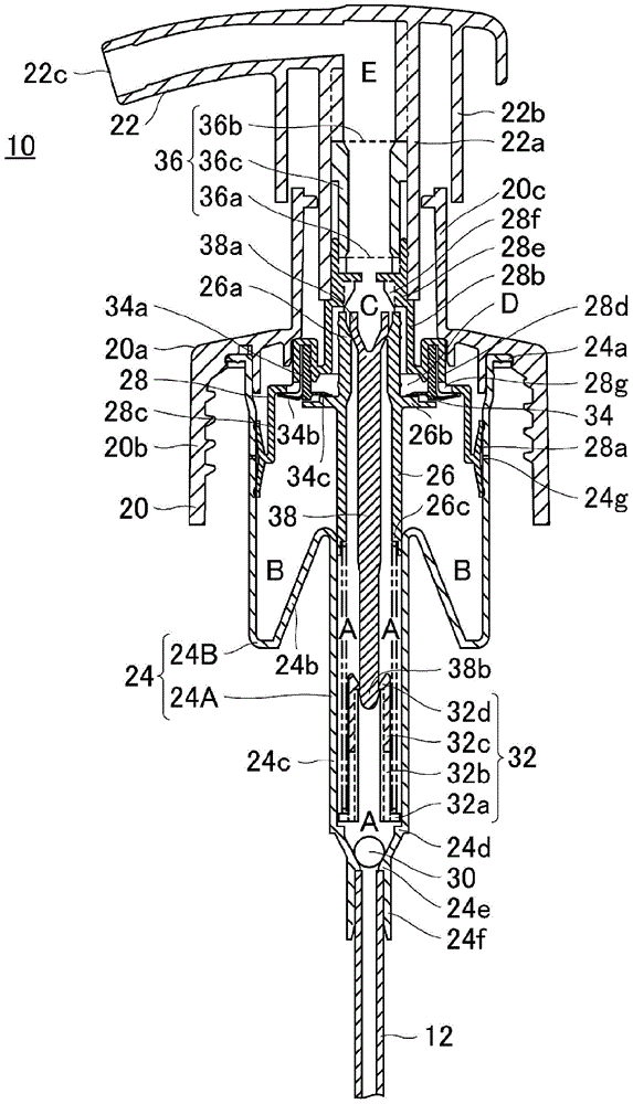
[0035] The pump-type spray container of this embodiment includes: a container body, which is used to accommodate liquid; a spray pump body, which is mounted on the mouth of the upper end of the container body in a detachable manner; a pipe body, which is connected to the spray pump body; The pump body communicates with and extends to the inside of the container main body.

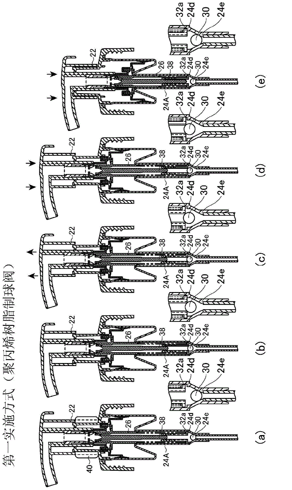
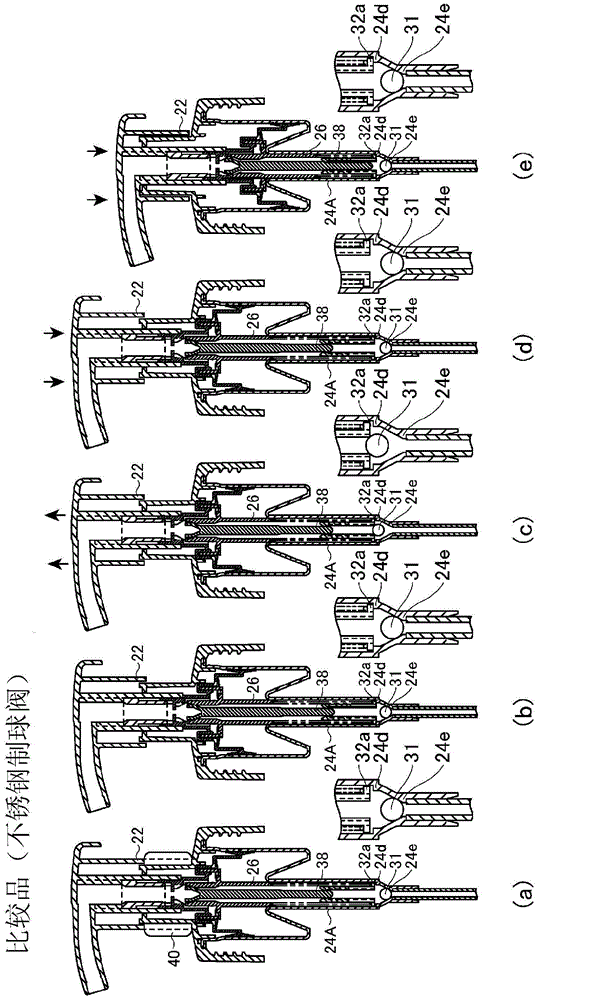
[0036] figure 1 A sectional view showing the discharge pump body 10 according to the first embodiment of the ...


PUM


Abstract

Provided is a pump-type discharge container that has a specific structure for preventing leakage of a liquid due to slight up-and-down motion of a nozzle, wherein when a nozzle head is initially depressed from a state in which the nozzle head is in its highest position, the ease of liquid discharge is improved. The container is configured so that, in a state in which a liquid chamber is filled with the liquid and the nozzle head is raised up as far upward as possible, a primary check valve opens communication between the liquid chamber and the main body of the container, and as a result, when the nozzle head is depressed to discharge the liquid from a state in which the nozzle head is raised up to its highest position, resistance to depressing of the nozzle head can be markedly reduced and the liquid can be easily discharged with a small amount of force because communication between the liquid chamber and the main body of the container has been opened.

Description

[0001] Associate application [0002] This application claims the priority of Japanese Patent Application No. 2012-25857 for which it applied on February 09, 2012, and uses the content here. technical field [0003] The present invention relates to a pump-type dispensing container, and more particularly to an improvement in usability of the pump-type dispensing container capable of preventing liquid from leaking due to a slight vertical movement of a nozzle during transportation or the like. Background technique [0004] Conventionally, there is known a pump-type discharge container in which liquid contained in the container body is discharged from a discharge port at the tip of the nozzle head by moving a nozzle head mounted above the container body up and down. In such a pump type discharge container, generally, a liquid chamber (a gap between the cylinder and the piston) is provided inside the discharge pump body, and a The primary check valve is provided with a secondar...

Claims


Application Information

Patent Timeline
Patent Type & Authority Applications(China)
IPC IPC(8): B65D83/76B65D47/34
CPCB05B11/3025B05B11/3073B05B11/3087B05B11/3001B05B7/0037B05B11/0064B05B11/1087B05B11/1001B05B11/1073B05B11/1014B05B11/1019
Inventor 植平庄治冈田知子阿部和也吉田治
Owner DAIWA CAN
Learn More