
Hot-forming die, press-forming device, and hot press-forming method

一种冲压成形、热成形的技术,应用在成型工具、制造工具、金属加工设备等方向,能够解决更换作业麻烦、冷却时间延迟、增加成本等问题,达到容易维护保养、强度优良的效果

Active Publication Date: 2012-09-19
NIPPON STEEL CORP
View PDF2 Cites 0 Cited by
  • Summary
  • Abstract
  • Description
  • Claims
  • Application Information

AI Technical Summary

Problems solved by technology

[0015] However, in the structure described in Patent Document 1, when an abnormality occurs in the supply passage, the entire mold in which the supply passage is formed must be replaced.
Especially in the structure that changes the diameter of the supply passage, abnormalities are likely to occur in the portion where the diameter changes
In addition, in the structure described in Patent Document 2, unless the punch reaches the bottom dead center, the pressure feeding of the coolant cannot be started, and an abnormal situation in which the cooling start time is delayed is likely to occur.
[0016] In this way, when replacing the entire die formed with the supply passage, not only the replacement work is troublesome, but also the cost is increased.

Method used


Image

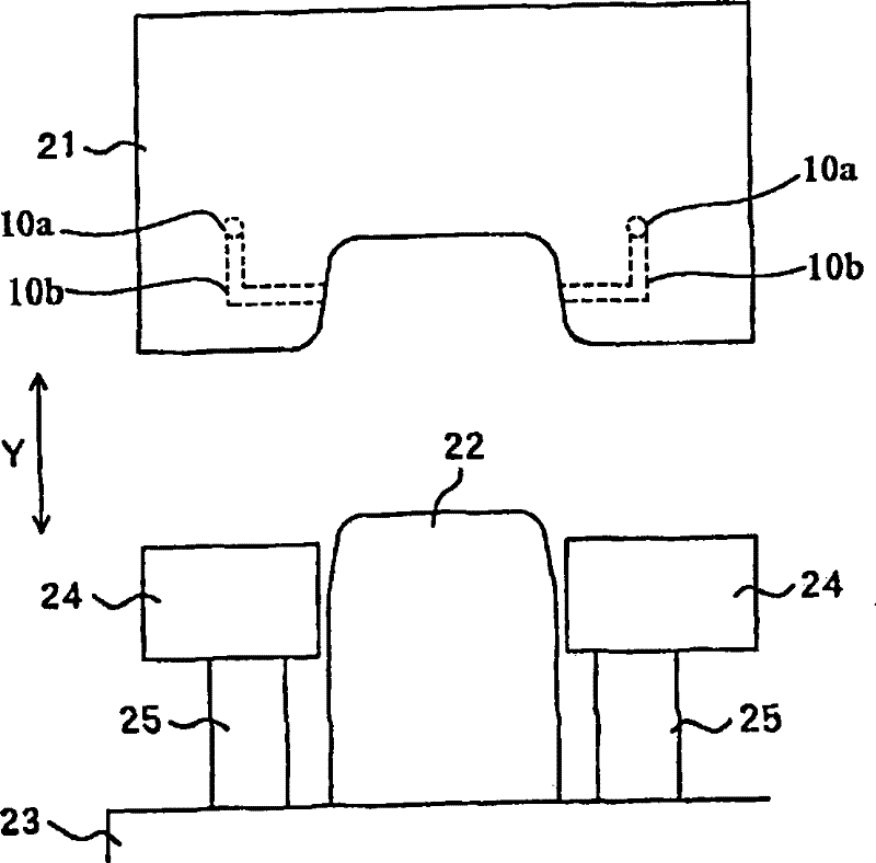
  • Hot-forming die, press-forming device, and hot press-forming method
  • Hot-forming die, press-forming device, and hot press-forming method
  • Hot-forming die, press-forming device, and hot press-forming method

Examples


Embodiment 1

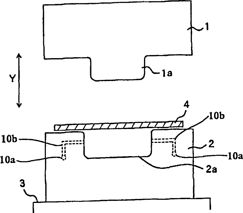
[0036] First, use figure 1 The forming apparatus of this embodiment will be described. in, figure 1 A schematic diagram showing the press forming apparatus of this embodiment.

[0037] figure 1 Among them, the punch 1 as the upper die can move along the arrow Y direction ( figure 1 In the up and down direction, that is, the up and down direction of the forming device) displacement. Furthermore, a die 2 serving as a lower die is fixed to a plate 3 . Such as figure 1 As shown by the dotted line of , supply passages (a main supply passage 10 a and branch supply passages 10 b to be described later) through which the coolant passes are provided inside the die 2 .

[0038] The flat metal plate 4 heated to 700 to 1000° C. by a heating furnace (not shown) is conveyed to the forming apparatus 5 having the above-mentioned structure by a conveying mechanism including a conveying robot or the like. When the metal plate 4 is placed on the die 2, the punch 1 is lowered.

[0039] Whe...

Embodiment 2

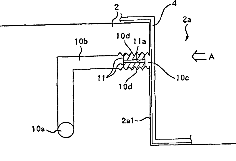
[0081] use below Figure 5 A forming apparatus according to Example 2 of the present invention will be described. in, Figure 5 It is a diagram showing a part of the die 2 , that is, an internal structure around a recess formed in the die 2 .

[0082] Only the parts different from the first embodiment will be described below, and the configurations not described are the same as those of the first embodiment. In this embodiment, the structure of the nozzle member and the branch supply passage is partly different from that of Embodiment 1.

[0083] The nozzle member 12 is formed of an elastically deformable material (for example, resin, rubber, ceramics, cork, glass), and the same passage hole as in the first embodiment is formed inside. Furthermore, the outer peripheral surface of the nozzle member 12 is substantially cylindrical.

[0084] The branch supply passage 10b has approximately the same diameter in all areas. That is, unlike the structure of Example 1, no threaded...

Embodiment 3

[0090] Below, use Figure 6 with Figure 7 A forming apparatus according to Example 3 of the present invention will be described. in, Figure 6 (A) is a longitudinal sectional view of the nozzle member used in the present embodiment, Figure 6 (B) is from one end ( Figure 6 (A) The direction of the arrow A1) The external view when looking at the nozzle part. and, Figure 7 (A) is a longitudinal sectional view of a nozzle member of another form of the present invention, Figure 7 (B) is from one end side ( Figure 7 (A) The direction of the arrow A2) The external view of the nozzle part.

[0091] Only the parts different from the first embodiment will be described below, and the configurations not described are the same as those of the first embodiment. In this embodiment, the structure of the nozzle member is different from Embodiment 1.

[0092] On the outer peripheral surface of the nozzle member 13, a threaded portion 10d formed on the inner peripheral surface of ...


PUM


Abstract

A hot-forming die for a press-forming device press-forms a heated metal plate (body to be formed) (4) and cools the body by jetting a refrigerant to the body. The hot-forming die has a main feeding passage (10a) for allowing the refrigerant to pass therethrough, branched feeding passages (10b) branched from the main feeding passage and having jetting openings (10c) for jetting the refrigerant to the outside of the die, and nozzle members (11) fixed to the jetting opening side of the branched feeding passages and limiting the passage amount of the refrigerant by using passage holes (11a) for allowing the refrigerant to pass therethrough. In a hot press-forming method, the refrigerant in the die is held on standby after being pressurized to a degree at which the refrigerant is not jetted, further pressurized at a predetermined timing during or after press working, and then jetted to the body.

Description

technical field [0001] The present invention relates to a thermoforming die used for forming a heated steel sheet, and a press forming apparatus provided with the thermoforming die. Background technique [0002] Conventionally, in order to obtain automobile parts or machine parts, a method of producing molded products by press-forming a sheet metal material at a low temperature has been used. However, it is difficult to obtain stamped products with complex shapes by the cold press forming method because the metal plate has a characteristic that its ductility decreases as its strength increases, and fractures (so-called cracks) occur. In addition, even for stamped products with simple shapes, elastic recovery (so-called springback) caused by the release of residual stress after forming is a problem, and good dimensional accuracy may not be obtained in some cases. [0003] As a technique for obtaining a high-strength formed product or formed part instead of the cold press for...

Claims


Application Information

Patent Timeline
Patent Type & Authority Patents(China)
IPC IPC(8): B21D37/16B21D22/20B21D24/00
CPCB21D22/02B21D37/16B21J1/06B21D22/20B21D24/00
Inventor 石森裕一岛哲男
Owner NIPPON STEEL CORP
Learn More