
Electrical load management and control method, system, equipment and medium

A technology of power load and management and control system, applied in the direction of power network operating system integration, information technology support system, electrical components, etc., can solve the problem of increasing power grid and circuit power supply pressure, unable to timely control the power load of equipment, and low efficiency of manual calculation And other issues

Pending Publication Date: 2021-09-07
FUJIAN NEBULA ELECTRONICS CO LTD
View PDF5 Cites 0 Cited by
  • Summary
  • Abstract
  • Description
  • Claims
  • Application Information

AI Technical Summary

Problems solved by technology

[0003] Battery testing uses charging and discharging equipment to charge and discharge the battery, and then conducts DCR testing (DC impedance high-power testing). However, traditionally, manual calculation of power is used to control the operation of charging and discharging equipment. Due to the energy and power of DCR testing They are all very large. The traditional method cannot timely control the power load of all equipment, and the efficiency of manual calculation is low, which often causes power overload and increases the power supply pressure of the power grid and circuits.

Method used


Image

  • Electrical load management and control method, system, equipment and medium
  • Electrical load management and control method, system, equipment and medium
  • Electrical load management and control method, system, equipment and medium

Examples


Embodiment 1

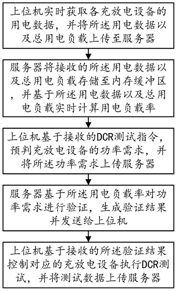
[0045] This embodiment provides a power load control method, such as figure 1 and Figure 5 shown, including the following steps:

[0046] Step S10, the upper computer obtains the power consumption data of each charging and discharging equipment in the factory area in real time, and uploads the power consumption data and the total power consumption load to the server; the total power consumption load is the maximum load that the factory area can bear; through Obtain the power consumption data in real time to ensure the stability of power consumption of all charging and discharging equipment in the factory area;

[0047] Step S20, the server stores the received power consumption data and the total power consumption load in the memory buffer, and calculates the power consumption load rate in real time based on the power consumption data and the total power consumption load; by storing the power consumption data and the total power consumption load The total power load is store...

Embodiment 2

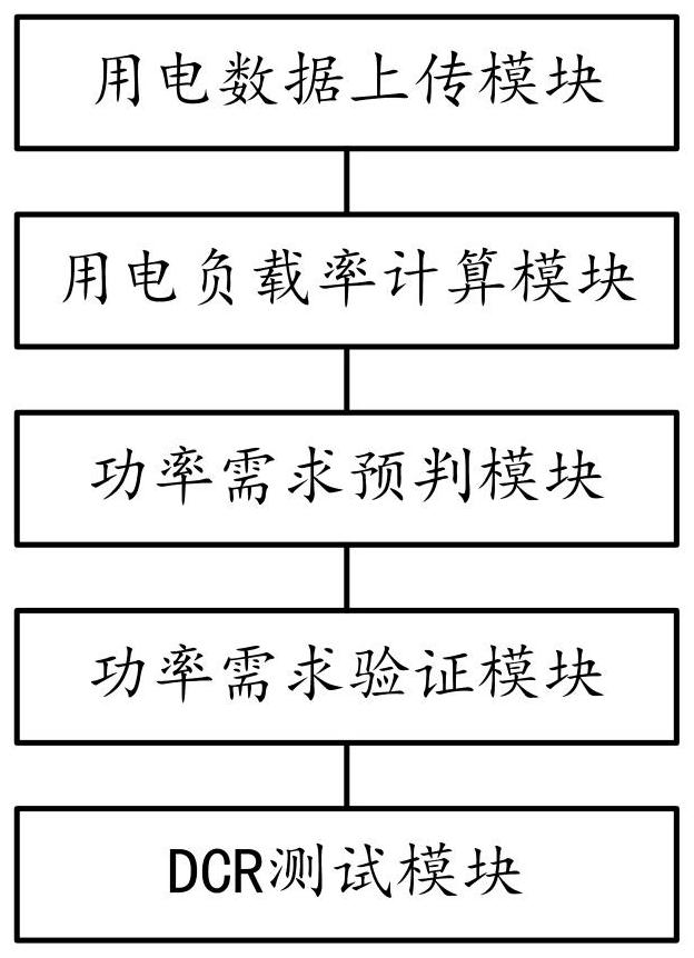
[0058] This embodiment provides an electric load control system, such as figure 2 and Figure 5 As shown, the following modules are included:

[0059] The power consumption data upload module is used for the upper computer to obtain the power consumption data of each charging and discharging equipment in the factory area in real time, and upload the power consumption data and the total power consumption load to the server; the total power consumption load is what the factory area can bear The maximum load; by obtaining the power consumption data in real time, it is convenient to ensure the power consumption stability of all charging and discharging equipment in the factory area;

[0060] The power consumption load rate calculation module is used for the server to store the received power consumption data and the total power consumption load in the memory buffer, and calculate the power consumption load rate in real time based on the power consumption data and the total power...

Embodiment 3

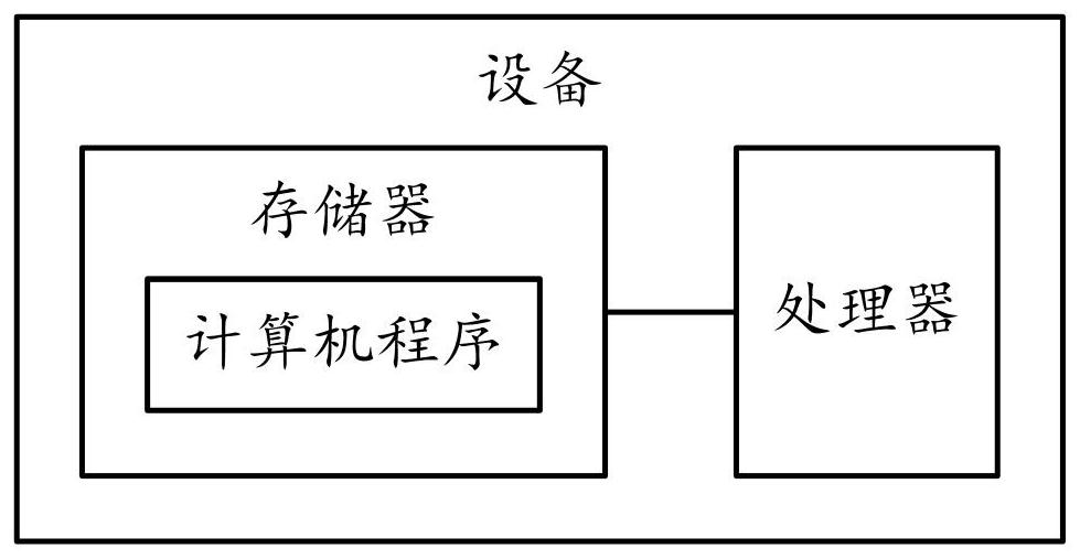
[0072] This embodiment provides a power load control device, such as image 3 As shown, it includes a memory, a processor, and a computer program stored in the memory and operable on the processor. When the processor executes the computer program, any implementation manner in Embodiment 1 can be realized.

[0073] Since the electronic device introduced in this embodiment is the device used to implement the method in Embodiment 1 of this application, based on the method described in Embodiment 1 of this application, those skilled in the art can understand the electronic device of this embodiment. Specific implementation methods and various variations thereof, so how the electronic device implements the method in the embodiment of the present application will not be described in detail here. As long as a person skilled in the art implements the equipment used by the method in the embodiment of the present application, it all belongs to the protection scope of the present applica...


PUM


Abstract

The invention provides an electrical load management and control method, system and equipment and a medium in the technical field of new energy automobiles. The method comprises the steps that S10, an upper computer obtains electrical data of each charging and discharging device in real time, and the electrical data and a total electrical load are uploaded to a server; S20, the server stores the received power consumption data and the total power consumption load in a memory buffer area, and calculates the power consumption load rate in real time based on the power consumption data and the total power consumption load; S30, the upper computer prejudges the power demand of the charging and discharging equipment based on the received DCR test instruction, and uploads the power demand to the server; S40, the server verifies the power demand based on the electricity load rate, generates a verification result and sends the verification result to the upper computer; and S50, the upper computer controls the corresponding charging and discharging equipment to execute a DCR test based on the received verification result, and uploads test data to the server. The system and the method have the advantages that comprehensive management and control of the electrical load are realized, and the electrical safety is greatly improved.

Description

technical field [0001] The invention relates to the technical field of new energy vehicles, in particular to a method, system, equipment and medium for controlling electric load. Background technique [0002] An electric vehicle (BEV) refers to a vehicle that is powered by a vehicle-mounted power supply, drives the wheels with a motor, and meets the requirements of road traffic and safety regulations. Due to its smaller impact on the environment than traditional cars, its prospects are widely optimistic. In order to ensure the safety of electric vehicles, the batteries of electric vehicles need to be tested. [0003] Battery testing uses charging and discharging equipment to charge and discharge the battery, and then conducts DCR testing (DC impedance high-power testing). However, traditionally, manual calculation of power is used to control the operation of charging and discharging equipment. Due to the energy and power of DCR testing They are all very large. The traditio...

Claims


Application Information

Patent Timeline
Patent Type & Authority Applications(China)
IPC IPC(8): H02J3/14H02J3/32
CPCH02J3/144H02J3/322H02J2203/10Y04S30/14Y04S30/12Y04S20/222Y02T90/167Y02B70/3225
Inventor 刘作斌陈方平刘涛吴林丽
Owner FUJIAN NEBULA ELECTRONICS CO LTD
Learn More