
Drive module of power supply system of buried sewage treatment equipment fan room

A technology for sewage treatment equipment and drive modules, which is applied to power cables with shielding/conducting layers, emergency protection circuit devices for limiting overcurrent/overvoltage, electrical components, etc. The adjustment of control parameters is not flexible enough, and the lightning protection measures are not good enough, so as to improve the safety of use, improve safety, and prevent lightning strikes

Inactive Publication Date: 2014-10-15
ZHUJI WOSI ENVIRONMENTAL PROTECTION TECH
View PDF9 Cites 0 Cited by
  • Summary
  • Abstract
  • Description
  • Claims
  • Application Information

AI Technical Summary

Problems solved by technology

[0005] There are deficiencies in the design of the above-mentioned fan room power supply system: First, the lightning protection measures are not good enough. When the lightning current is too strong, a small part of the lightning current may enter the load equipment, which will cause the load equipment to be damaged under the impact of the lightning current residual voltage. , which makes the system less secure and greatly shortens its service life; second, the anti-interference measures are not ideal, and the load equipment is easily disturbed by factors such as power supply and external environment, which has a great impact on the stable operation of the load equipment; The reason is that the control is not convenient enough, and the adjustment of its control parameters is not flexible enough to meet the needs of users well.

Method used


Image

  • Drive module of power supply system of buried sewage treatment equipment fan room
  • Drive module of power supply system of buried sewage treatment equipment fan room
  • Drive module of power supply system of buried sewage treatment equipment fan room

Examples


Embodiment Construction

[0022] In the following description, numerous specific details are set forth in order to provide a thorough understanding of the present invention. However, the present invention can be implemented in many other ways different from those described here, and those skilled in the art can make similar extensions without violating the connotation of the present invention, so the present invention is not limited by the specific embodiments disclosed below.

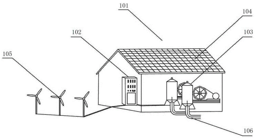
[0023] see figure 1 , is a schematic diagram of the fan room of the buried sewage treatment equipment. The fan room of the buried sewage treatment equipment includes a machine room body 101: the machine room body 101 is spliced ​​by color steel sandwich panels, has a simple structure, is convenient to disassemble and assemble, and has low production cost; the force-bearing frame is made of section steel and has high structural strength; The machine room body 101 is provided with shutters, which have good ventilation and heat d...


PUM


Abstract

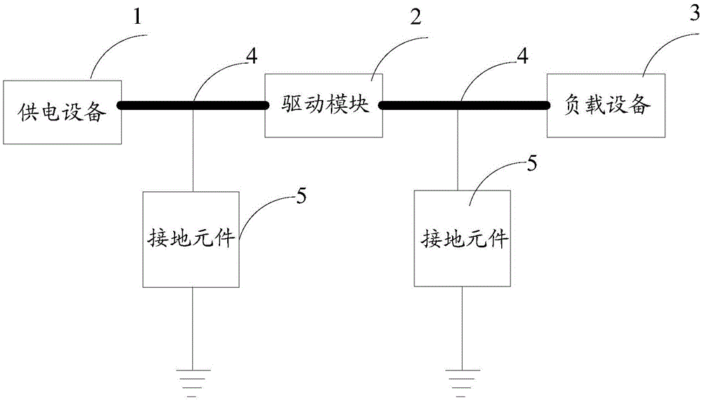
The invention discloses a drive module of a power supply system of a buried sewage treatment equipment fan room. The drive module is arranged between a power supply device and a load device and used for alternating current provided by the power supply device into alternating current or direct current required by the load device. The drive module comprises a rectifying circuit for converting alternating current into direct current, a filter circuit for achieving smooth filtering and energy storage effects of the direct current, an inverter circuit for finishing conversion from the direct current to the alternating current so as to achieve frequency and voltage regulation, a power factor regulation circuit arranged between the rectifying circuit and the filtering circuit, a microprocessor circuit and a man-machine interface circuit connected to the input end of the microprocessor circuit, wherein a power factor correction end of the microprocessor circuit is connected with the power factor regulation circuit, and the drive signal end of the microprocessor circuit is connected with the inverter circuit. The drive module of the power supply system of the buried sewage treatment equipment fan room can improve the performance of a power supply system on at least one aspect of safety, anti-interference or controllability and the like.

Description

technical field [0001] The invention relates to a sewage treatment technology, in particular to a power supply system and ancillary facilities of a fan room of an underground sewage treatment equipment. Background technique [0002] The buried sewage treatment equipment is a kind of sewage biological treatment system with biofilm as the main body of purification. It has the characteristics of low consumption, stable operation and convenient maintenance, so it has a wide application prospect and promotion value. [0003] Typical buried sewage treatment equipment includes grid wells, regulating tanks, primary sedimentation tanks, dynamic oxidation contact tanks, clarifiers and fan rooms connected to the dynamic oxidation contact tanks; the dynamic oxidation contact tanks include reactors The main body, the inner shell of the reactor, and the rotary-cut agitator; the inner shell of the reactor is arranged inside the main body of the reactor, and its bottom opening communicates...

Claims


Application Information

Patent Timeline
Patent Type & Authority Applications(China)
IPC IPC(8): H02M5/458H02M1/12H02H9/02H01B9/02
Inventor 周磊
Owner ZHUJI WOSI ENVIRONMENTAL PROTECTION TECH
Learn More