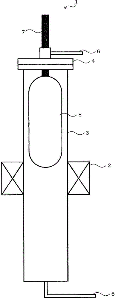
Sintering apparatus

A technology of sintering device and furnace core tube, which is applied in glass forming, lighting and heating equipment, furnace components, etc., and can solve problems such as leakage

Inactive Publication Date: 2014-10-15
SHIN ETSU CHEM CO LTD
View PDF7 Cites 8 Cited by
  • Summary
  • Abstract
  • Description
  • Claims
  • Application Information

AI Technical Summary

Problems solved by technology

This is because a small amount of warping of the lid or the flange of the furnace tube can cause a leak

Method used


Image

  • Sintering apparatus
  • Sintering apparatus
  • Sintering apparatus

Examples


Embodiment 1

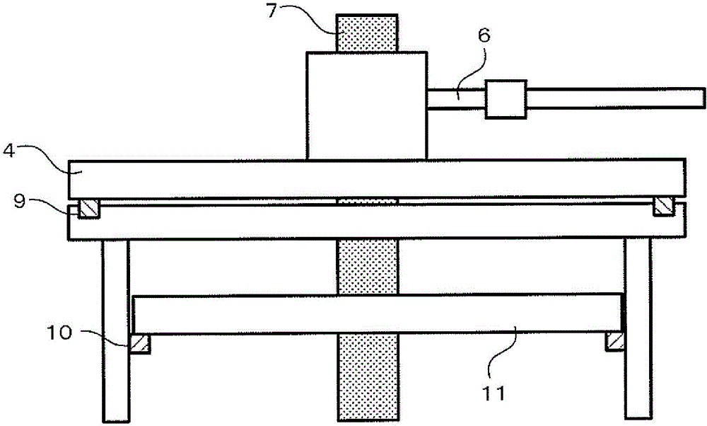
[0023] figure 2 It is a schematic diagram of the structure near the cover 4 used in Example 1. Such as figure 2 As shown, a protrusion 10 is provided near the upper end of the inner wall of the furnace core tube 3 , and an inner cover 11 supported by the protrusion is provided to divide the upper end region of the furnace core tube 3 into two. The gap between the inner cover 11 and the furnace core tube 3 is 0.5 mm, and the gap between the inner cover 11 and the shaft body 7 on which the soot deposit body 8 hangs down is 1 mm. These gaps form a gas flow path that communicates with the upper and lower halves of the inner cover 11, and does not completely block the flow of atmospheric gas. When the soot deposited body 8 was sintered in the same manner as in the comparative example with such a structure, it was found that no minute air bubbles as seen in the comparative example remained in the obtained glass body.

[0024] It can be seen that by making the sum of the cross-s...

Embodiment 2

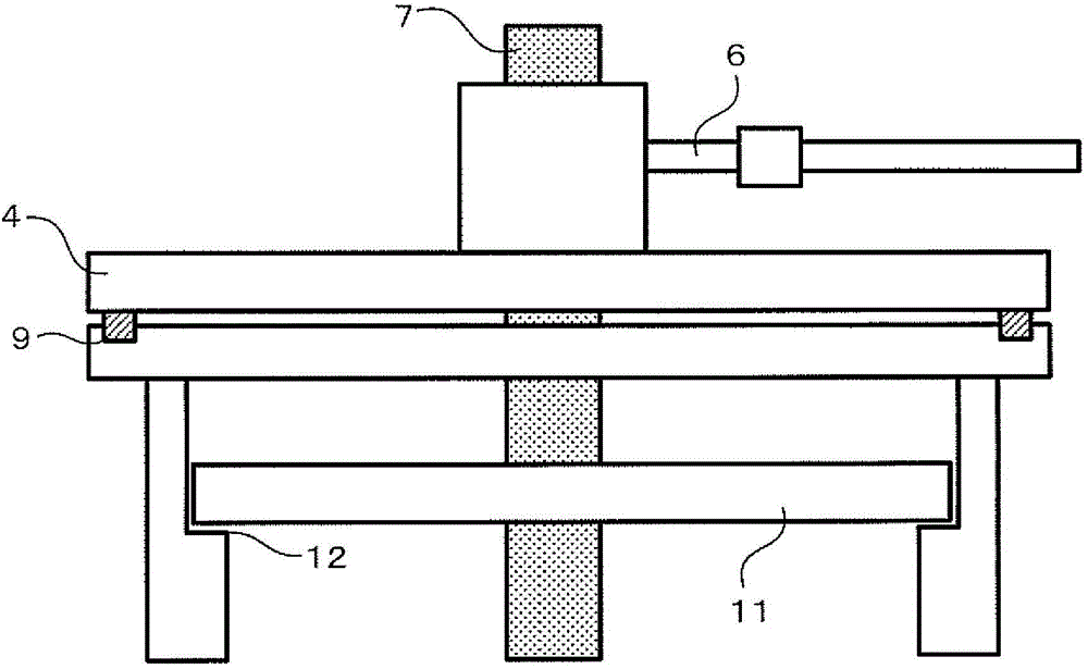
[0027] image 3 It is a schematic diagram of the structure near the cover 4 used in Example 2. Such as image 3 As shown, a step 12 is provided near the upper end of the inner wall of the furnace core tube 3, and an inner cover 11 supported by the step 12 is provided to divide the upper end area of ​​the furnace core tube 3 into two along the upper and lower sides. The gap between the inner cover 11 and the shaft body 7 on which the soot deposit body 8 hangs down is 1 mm. This gap forms a gas flow path connecting the upper and lower halves of the inner cover 11, and does not completely block the flow of atmospheric gas. When the soot deposited body 8 was sintered in the same manner as in the comparative example with this structure, it was found that no minute air bubbles as seen in the comparative example remained in the obtained glass body.


PUM


Abstract

The invention provides a sintering apparatus for manufacturing quartz glass by heating and sintering a soot deposition body formed of a powder containing silicon dioxide. The sintering apparatus comprises a furnace core tube having an opening in a top end through which the soot deposition body is inserted, and has atmospheric gas introduced therein from below and expelled upward; a shaft from which the soot deposition body hangs; a lid that has the shaft inserted therethrough and can cover the opening; a heating furnace that heats the soot deposition body; an internal lid in a top portion of the furnace core tube that divides the top portion of the furnace core tube into an upper region and a lower region; and a gas flow path that connects the two regions to each other and has the atmospheric gas flow therethrough. Total cross-sectional area, relative to movement direction of the atmospheric gas, of the gas flow path is less than cross-sectional area, relative to movement direction of the atmospheric gas, of the furnace core tube.

Description

technical field [0001] This invention relates to the manufacture of high purity synthetic silica glass for use in optical fibers and the like. Background technique [0002] As a method for producing synthetic quartz glass, Japanese Patent Application Laid-Open No. 2012-250887 describes the method of heating and sintering a soot deposited body produced by depositing fine silica powder produced by reacting a silicon compound in a sintering furnace. method. A VAD method, an OVD method, etc. are known as the manufacturing method of a soot deposit. The structure of the sintering furnace includes, for example, a heating furnace and a core tube, and a gas suitable for the sintering atmosphere is introduced or discharged into the core tube. The above-mentioned soot-deposited body is introduced into the furnace tube and heated in an appropriate atmosphere to become a transparent glass body. In order to maintain the atmosphere during sintering in an appropriate state, the furnace c...

Claims


Application Information

Patent Timeline
Patent Type & Authority Applications(China)
IPC IPC(8): C03B19/06
CPCF27B1/10F27D3/0084C03B37/0146F27D7/06
Inventor 井上大内田一也
Owner SHIN ETSU CHEM CO LTD
Why Eureka
Try Eureka