
Shield tube push bench with super-large rectangular cross section

A technology with a rectangular section and a shield roof, which is applied to mining equipment, earthwork drilling, tunnels, etc., can solve the problems of high precision control of the pipe jacking axis, uneven thrust of the tunneling surface, and difficult control of surface settlement, etc. The effect of surface settlement, high construction efficiency, and low equipment cost

Active Publication Date: 2014-10-08
CHINA RAILWAY ENGINEERING EQUIPMENT GROUP CO LTD
View PDF6 Cites 30 Cited by
  • Summary
  • Abstract
  • Description
  • Claims
  • Application Information

AI Technical Summary

Problems solved by technology

[0004] This project is the first underground excavation construction project with a super-large rectangular section of 10.12m×7.27m in China. There is no similar construction case for reference; the excavation section is large, and the state of uneven thrust on the excavation surface is not easy to adjust; the covering soil is very shallow, and the maximum buried depth of the tunnel It is 4.2 meters, which makes the surface settlement difficult to control; there are two motor vehicle lanes in the middle of the project, and two non-motor vehicle lanes are excavated in parallel on both sides. very difficult

Method used


Image

  • Shield tube push bench with super-large rectangular cross section
  • Shield tube push bench with super-large rectangular cross section
  • Shield tube push bench with super-large rectangular cross section

Examples


Embodiment Construction

[0022] The present invention will be further described below in conjunction with drawings and embodiments.

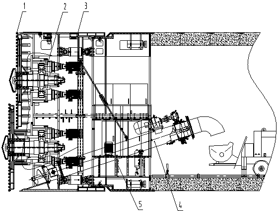
[0023] like figure 1 As shown, the super-large rectangular section shield pipe jacking machine of the present invention includes: a cutter head device 1, an independent drive system 2, a rectangular shield 3 supporting the entire equipment, a screw conveyor 4 and a supporting system 5.

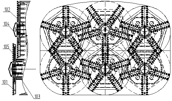
[0024] like figure 2 As shown, the cutterhead device 1 is a combined cutterhead, consisting of six small spoke-type cutterheads, wherein the three spoke-type small cutterheads of the front small cutterhead 101 are distributed on the same front plane in an inverted shape, and the rear small cutterheads The three spoke-type small cutterheads of 102 are distributed on the same rear plane in the shape of genuine products, so that the cutting areas overlap and overlap each other. Each spoke-type small cutter head structure is mainly composed of five main knife beams and a central fishtail...


PUM


Abstract

The invention relates to a shield tube push bench with a super-large rectangular cross section. The tube push bench comprises a cutterhead device, a driving system, a shield structure, a screw conveyer and a back up system, wherein the section of the shield structure is rectangular, and the upper part of the shield structure is in the shape of an arch camber; the shield structure comprises a front shield, error correcting cylinders, a tail shield, adjustable hinged seals and an appearing cylinder; the front shield supporting and driving system is characterized in that the front shield is connected with the tail shield through at least two sets of error correcting cylinders, and the appearing cylinder is arranged at the rear end of the tail shield. In order to further improve the structure of the push bench, the cutterhead device is a combined cutterhead, and can ensure that the earth pressure of the front shield and a tunnelling surface is balanced, and disturbance to an earth layer is small; the driving system is an independent drive system, and a torque can be regulated in a real time manner according to a geological condition. Therefore, the push bench is high in construction efficiency, and small in disturbance to a bottom layer, the ground surface settlement is decreased, the construction reliability is improved, the deslagging efficiency is improved, and the assembling, disassembling, operation and control of the whole tube push bench is convenient and safe; the construction cost of the tube push bench is low, and the tube push bench is economical and practical.

Description

technical field [0001] The invention belongs to the technical field of tunnel construction equipment, in particular to shield pipe jacking equipment. Background technique [0002] Shield technology does not require a large number of demolition and excavation of the ground. There is no noise, no dust, and no disturbance to the people on the ground. All of them are automatically controlled and the progress of the project is fast. Therefore, it is a method that can reduce engineering pollution and save a lot. Construction technology for project investment. Among them, the pipe jacking machine is a highly mechanized and automated excavation and lining complete set of equipment that adopts the shield method and integrates mechanical, electronic, hydraulic, laser and control technologies. [0003] In the motorway tunnel project under Zhengzhou Crossing Zhongzhou Avenue, the construction site is located in the floodplain area of ​​the Yellow River, with roads on the surface and Q...

Claims


Application Information

Patent Timeline
Patent Type & Authority Applications(China)
IPC IPC(8): E21D9/08
Inventor 李建斌范磊贾连辉卓兴建董艳萍王小涛龚廷民
Owner CHINA RAILWAY ENGINEERING EQUIPMENT GROUP CO LTD
Learn More