Breaker, undervoltage tripping device, and under/overvoltage tripping device

A tripping device and undervoltage technology, which is applied in the protection of undervoltage or no voltage, and the protection of overvoltage, can solve the problems of cost increase and achieve cost reduction, miniaturization reduction, and delay The effect of time characteristic maintenance

Active Publication Date: 2014-10-01
PANASONIC INTELLECTUAL PROPERTY MANAGEMENT CO LTD
View PDF8 Cites 5 Cited by
  • Summary
  • Abstract
  • Description
  • Claims
  • Application Information

AI Technical Summary

Problems solved by technology

For this reason, the size of the device is increased, and the cost is also increased

Method used


Image

  • Breaker, undervoltage tripping device, and under/overvoltage tripping device
  • Breaker, undervoltage tripping device, and under/overvoltage tripping device
  • Breaker, undervoltage tripping device, and under/overvoltage tripping device

Examples


no. 1 approach )

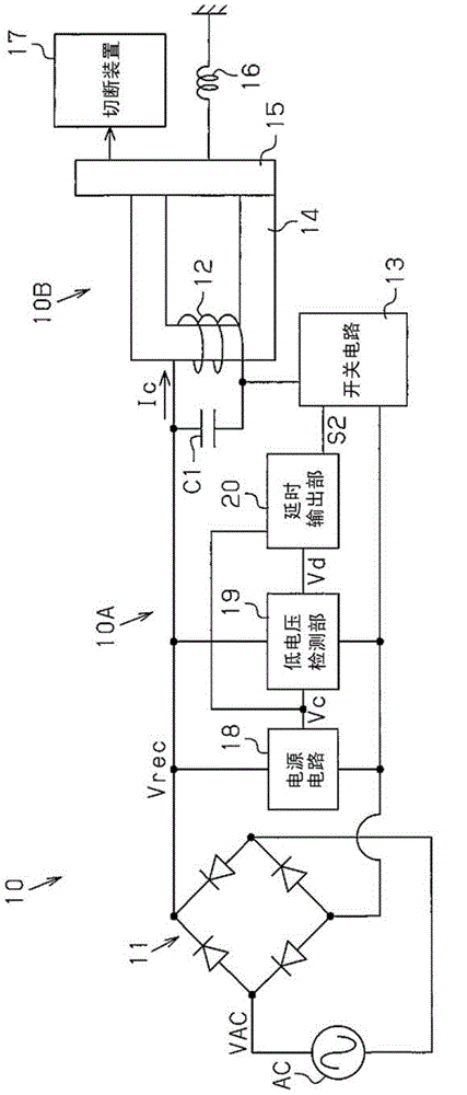
[0062] Below, according to Figure 1 ~ Figure 4 , the first embodiment of the circuit breaker provided with the undervoltage release device will be described.

[0063] Such as figure 1 As shown, the circuit breaker 10 includes an undervoltage tripping device 10A and a disconnection mechanism 10B. 10 A of undervoltage tripping devices are connected to commercial power supply AC. The rectification circuit 11 performs full-wave rectification on the commercial power supply voltage VAC supplied from the commercial power supply AC to generate a full-wave rectified voltage Vrec.

[0064] The full-wave rectified voltage Vrec is supplied to one end of the coil 12 wound around the fixed pole 14 . The other end of the coil 12 is connected to a switch circuit 13 . In addition, a capacitor C1 is connected in parallel between both terminals of the coil 12 . An exciting current Ic is supplied to the coil 12 based on the full-wave rectified voltage Vrec. The capacitor C1 smoothes the e...

no. 2 approach )

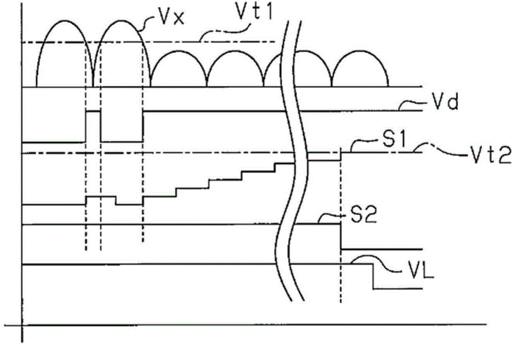
[0089] Figure 5 Shows the second embodiment. In the second embodiment, the low-voltage detection unit 19 is configured such that during a predetermined time t1 after the low-voltage detection signal Vd temporarily rises to the H level (that is, after the comparison voltage Vx temporarily falls below the threshold voltage Vt1 ), Even if the comparison voltage Vx exceeds the threshold voltage Vt1, the low voltage detection signal Vd is maintained at the H level.

[0090] With this configuration, even when high-frequency noise is carried on the full-wave rectified voltage Vrec, the output level of the low-voltage detection signal Vd can be stabilized. In addition, there is no need to provide a filter for removing high-frequency noise in the input section of the low-voltage detection section 19, so that the cost can also be reduced.

no. 3 approach )

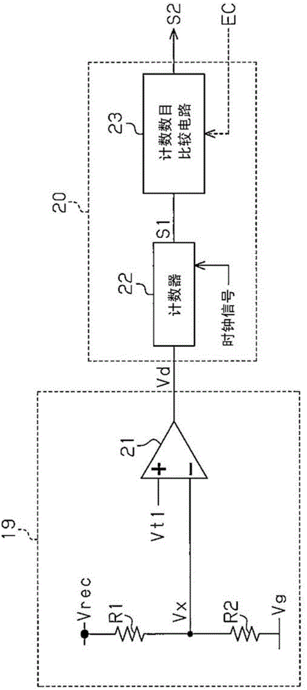
[0092] Image 6 shows the third embodiment. In the third embodiment, the count number comparison circuit 23 is configured based on a control signal EC from an external device not shown (see figure 2 ) to adjust the threshold voltage Vt2 (delayed output threshold).

[0093] With this configuration, the control signal EC can adjust the delay time from when the excitation low voltage detection signal Vd rises to the H level until the excitation current cutoff signal S2 falls to the L level.


PUM


Abstract

The invention discloses an undervoltage tripping device of a breaker. The undervoltage tripping device comprises a low voltage detection part, which can be used to output low voltage detection signals when the commercial power supply voltage is the undervoltage; a time-delay output part, which is used to output the excitation current cutting signal when the low voltage detection signals is output in the continuous predetermined period; a switch circuit,which is used to supply the coil with the excitation current based on the cut-off excitation current cutting signal. The low voltage detection part comprises a comparator capable of comparing the comparison voltage and the low voltage threshold value based on the commercial power supply voltage in order to generate the low voltage detection signals. The time-delay output part comprises a counter, which can be used to count based on the input of the low voltage detection signals and output the counted value as the time-delay signal; and a counting number comparison circuit, which can be used to generate the excitation current cutting signal based on the comparison of the time-delay signal and the time-delay output threshold value.

Description

technical field [0001] The present invention relates to a circuit breaker for cutting off the supply of a commercial power supply, and an undervoltage tripping device and an overvoltage / undervoltage tripping device used in the circuit breaker. Background technique [0002] When the power supply voltage of the commercial power supply falls below a predetermined voltage, the undervoltage release device of the circuit breaker cuts off the supply of the power supply voltage from the commercial power supply to the load equipment. [0003] Figure 12 A conventional example of a circuit breaker equipped with an undervoltage release device is shown. A commercial power supply voltage VAC supplied from a commercial power supply AC is supplied to the rectifier circuit 1 via a sensitivity adjustment device 4 composed of a capacitor or a resistor. The rectifier circuit 1 full-wave rectifies the commercial power supply voltage VAC to generate a full-wave rectified voltage Vrec, and an ex...

Claims


Application Information

Patent Timeline
Patent Type & Authority Applications(China)
IPC IPC(8): H02H3/24H02H3/20
Inventor 山添宏一田中毅
Owner PANASONIC INTELLECTUAL PROPERTY MANAGEMENT CO LTD
Why Eureka
Try Eureka