Motor control circuit and refrigerator

A motor control and circuit technology, which is applied in ice making, ice making, household refrigeration equipment, etc., can solve the problems of cost increase and circuit board enlargement, and achieve the effect of cost reduction and miniaturization reduction

Inactive Publication Date: 2018-10-23
NIPPON DENSAN CORP
View PDF5 Cites 0 Cited by
  • Summary
  • Abstract
  • Description
  • Claims
  • Application Information

AI Technical Summary

Problems solved by technology

As a result, the size of the circuit board on which the control unit is mounted increases and the cost increases.

Method used


Image

  • Motor control circuit and refrigerator
  • Motor control circuit and refrigerator
  • Motor control circuit and refrigerator

Examples


Embodiment Construction

[0016] Hereinafter, exemplary embodiments of the present invention will be described with reference to the drawings. Here, a refrigerator will be described as an example of an electric appliance equipped with a motor control circuit.

[0017]

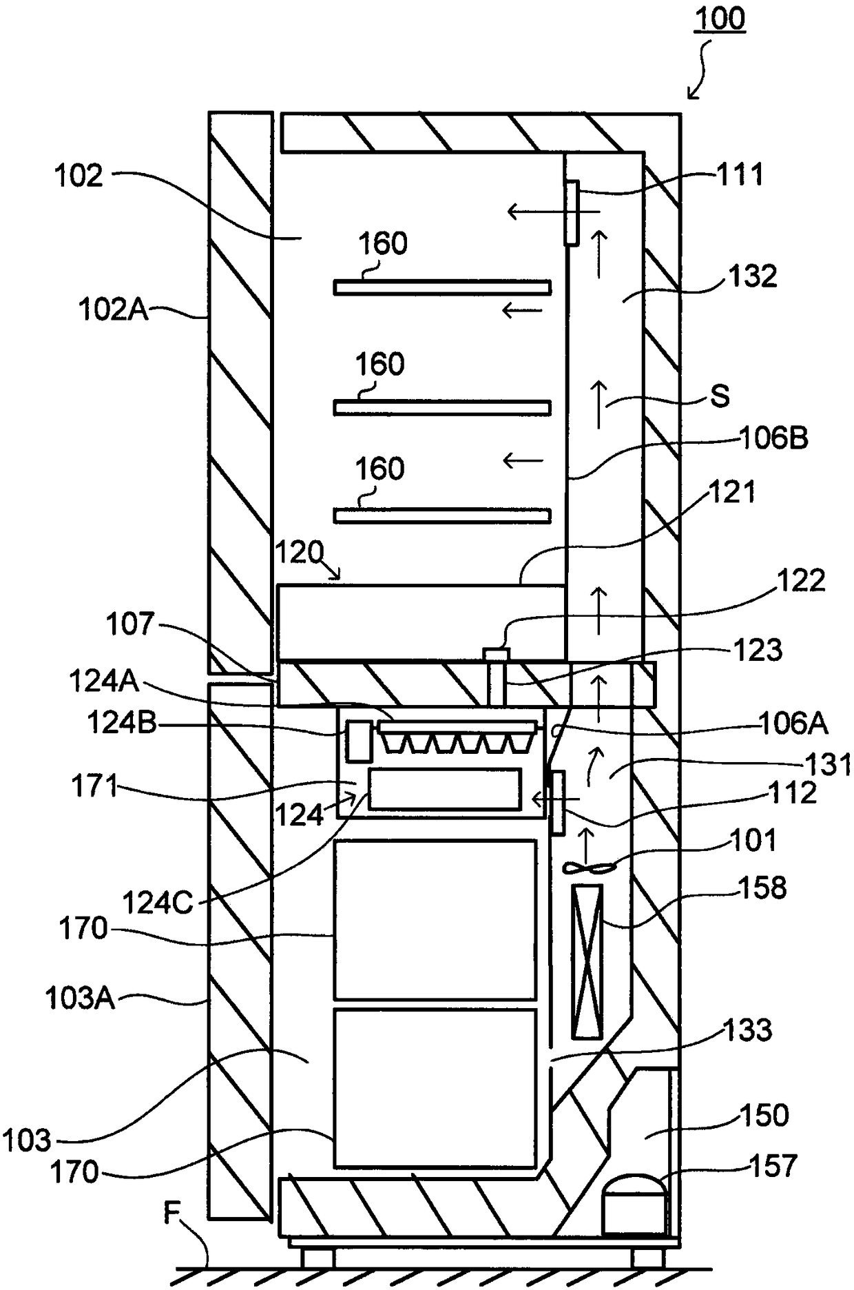
[0018] figure 1 It is a schematic side cross-sectional view of refrigerator 100 according to one embodiment of the present invention. In addition, arrow S shows the flow of cold air. Refrigerator 100 is installed on the floor surface F. As shown in FIG. Refrigerator 102 is arranged on the upper part of refrigerator 100 and opened and closed by door 102A. Below refrigerator 100, freezer compartment 103 that is opened and closed by door 103A is arranged.

[0019] The cold room 102 is maintained at a cold temperature (for example, 3° C.), and the stored items are kept cold. In the cold storage room 102, a plurality of trays 160 on which stored goods are placed are installed. A plurality of storage pockets (not shown) are provided i...


PUM


Abstract

The invention provides a motor control circuit and a refrigerator. The motor control circuit comprises a microcomputer, a driver in which signals output by a microcomputer are input as input signals and outputs the input signals to a plurality of driving objects according to the input signals, and a switch portion which determines whether to switch the output signals output by the driving objectsthrough control of the microcomputer.

Description

technical field [0001] The invention relates to a motor control circuit and a refrigerator. Background technique [0002] Conventionally, various electric appliances such as refrigerators are mounted with various motors, and a motor control circuit for driving and controlling the motors is also mounted. An example of a motor control circuit mounted in a refrigerator is disclosed in Japanese Laid-Open Publication No. 2015-94510. [0003] The refrigerator of Patent Document 1 includes an ice making motor, a water supply motor, and a control unit for driving and controlling these motors. The ice making motor is a motor that drives the ice making tray of the ice making device. The water supply motor is built into the water supply pump. When the water supply motor is driven, the water supply pump sucks water from the water supply tank and supplies the water to the ice making tray. [0004] The control unit has an ice-making motor driver that drives the ice-making motor, a wat...

Claims


Application Information

Patent Timeline
Patent Type & Authority Applications(China)
IPC IPC(8): F25D23/12F25D17/06F25D29/00F25C1/00
CPCF25C1/00F25D17/062F25D23/12F25D29/00
Inventor 青木顺一
Owner NIPPON DENSAN CORP
Why Eureka
Try Eureka