Speed reducer

A technology for reducers and gearboxes, which is applied in the direction of mechanical equipment, transmission parts, gear transmissions, etc., can solve the problems of rising device costs, complex overall structure, and unsatisfactory cooling performance, and achieve improved stirring performance and cooling The effect of performance improvement

Inactive Publication Date: 2010-10-13
SUMITOMO HEAVY IND LTD
View PDF7 Cites 6 Cited by
  • Summary
  • Abstract
  • Description
  • Claims
  • Application Information

AI Technical Summary

Problems solved by technology

[0008] However, even if the internal cooling method with the above-mentioned structure is used in a reducer incorporated in a paper machine that operates continuously for 24 hours, for example, it cannot be said that sufficient cooling performance is satisfied.
However, the external cooling method complicates the overall structure and increases the cost of the device

Method used


Image

  • Speed reducer
  • Speed reducer
  • Speed reducer

Examples


Embodiment Construction

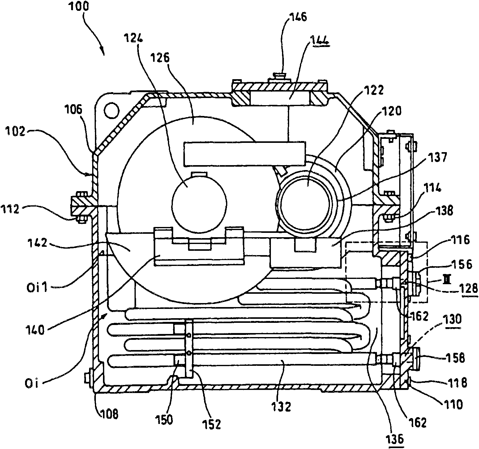
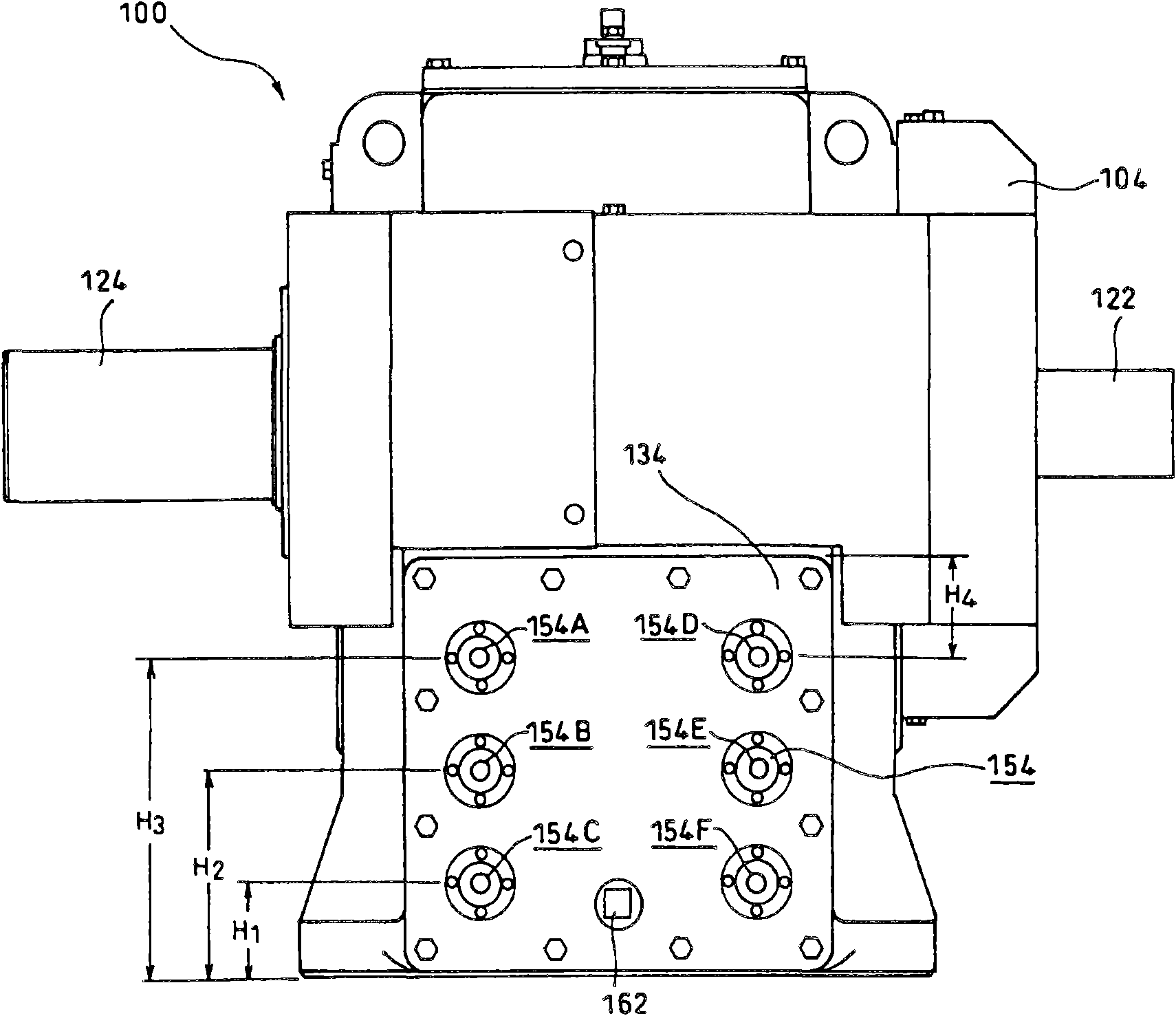
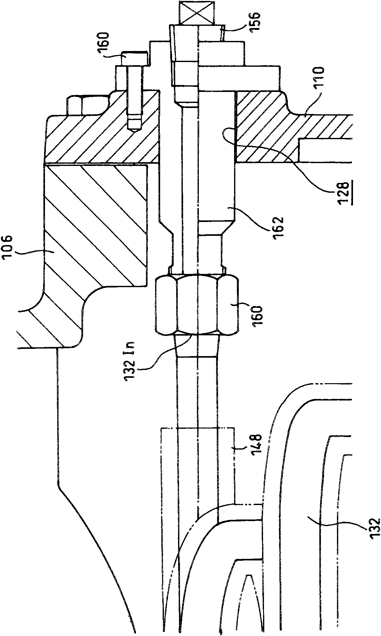
[0024] figure 1 It is a longitudinal cross-sectional view of the reduction gear 100 which concerns on an example of embodiment of this invention. Furthermore, in figure 2 Shows figure 1 A side view of the reducer 100 is shown, in image 3 Shows figure 1 A partial enlarged view of the reducer 100 shown in the direction view III.

[0025] First, the overall structure of the reduction gear 100 will be described.

[0026] The reduction gear 100 includes a gear transmission 102 . The housing 104 of the gear box 102 includes an upper cover 106 , a lower cover 108 and a side cover 110 .

[0027] The upper side cover 106 and the lower side cover 108 are fastened by bolts 112 and 114 . In addition, the lower side cover 108 and the side cover 110 are fastened with bolts 116 and 118 .

[0028] The gear case 102 has a cooling medium introduction hole 128 and an outlet hole 130 on the side surface on the side of the high-speed gear (small-diameter gear) 120 inside the gear case...


PUM


Abstract

The present invention provides a speed reducer which has high cooling performance though adopting an inner cooling mode and obtains miniaturization of the speed reducer and reduction of cooling cost. In the speed reducer (100) which is provided with a gearbox (102), the gearbox (102) comprises the following components: an introducing hole (128) of the cooling medium of lubricant (Oi); a discharging hole (130) of the cooling medium; cooling tubing (132) for guiding out the cooling medium which is introduced through the introducing hole (128) to the discharging hole (130). Furthermore the cooling tubing (132) is arranged in parallel relatively to a surface (Oil) of the lubricant Oi in the gearbox (102) and is arranged to a plurality of layers in a direction vertical with the surface Oil, wherein the tubing (132) is serpentine when observed from a specific horizontal direction.

Description

technical field [0001] This application claims priority based on Japanese Patent Application No. 2009-96080 filed on April 10, 2009. The entire contents of this application are incorporated herein by reference. [0002] The present invention relates to a reducer. Background technique [0003] Conventionally, as a cooling method of a reducer, there are known a method in which the lubricant flows out of the gear case of the reducer to cool the lubricant itself outside the outside cooling method, and a method of disposing a pipe which An internal cooling method in which a cooling medium is passed through the lubricant in the gear transmission, and the lubricant is cooled in the gear transmission. Compared with the external cooling method, the cooling system of this internal cooling method is sufficiently low-cost and small-sized, but has low cooling performance. [0004] However, since the internal cooling method has the above-mentioned advantages, it is introduced into many...

Claims


Application Information

Patent Timeline
Patent Type & Authority Applications(China)
IPC IPC(8): F16H57/04F16H1/06
CPCF16H57/0417
Inventor 山崎泰正林良树
Owner SUMITOMO HEAVY IND LTD
Why Eureka
Try Eureka