
Digital open loop temperature compensation system of optical module laser device

A technology of temperature compensation and laser, which is applied in the field of optical communication, can solve problems such as module failure and failure, power consumption environment temperature rise, and optical module power consumption increase, so as to avoid the risk of performance degradation and failure, and reduce power consumption. consumption, the effect of reducing power consumption

Active Publication Date: 2014-10-01
成都新易盛通信技术股份有限公司
View PDF6 Cites 22 Cited by
  • Summary
  • Abstract
  • Description
  • Claims
  • Application Information

AI Technical Summary

Problems solved by technology

[0005] Although this closed-loop method can stabilize the optical power and extinction ratio, as the temperature rises, the bias current and modulation current will increase sharply, the power consumption of the optical module will increase, and the increase in power consumption will aggravate the rise in ambient temperature. High, such a vicious cycle leads to a decrease in the performance of the module, and makes the module prone to failure and failure in a high temperature environment

Method used


Image

  • Digital open loop temperature compensation system of optical module laser device
  • Digital open loop temperature compensation system of optical module laser device
  • Digital open loop temperature compensation system of optical module laser device

Examples


Embodiment Construction

[0028] The present invention will be further described in detail below in conjunction with test examples and specific embodiments.

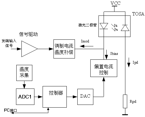
[0029] The invention provides a digital open-loop temperature compensation system for an optical module laser, including a digital open-loop temperature compensation power control circuit, an open-loop temperature compensation extinction ratio control circuit and a laser system parameter monitoring circuit; greatly reducing the power consumption of the transmitting part of the optical module , to avoid performance degradation and failure of the laser in a high temperature environment.

[0030]The system circuit block diagram of the digital open-loop temperature compensation power control circuit and the open-loop temperature compensation extinction ratio control circuit is as follows: figure 1 As shown, the system includes three parts, which are temperature compensation power control circuit, temperature compensation extinction ratio control cir...


PUM


Abstract

The invention relates to the field of optical communication, in particular to the laser temperature compensation technology, and discloses a digital open loop temperature compensation system of an optical module laser device. Temperature compensation is carried out on the laser device in an optical module through a digital open loop circuit to guarantee the stable output light power and the stable extinction ratio. Meanwhile, the operating temperature, the bias currents, the backlight currents, the operating voltage and the light collection power value of the digital open loop temperature compensation system are effectively monitored in real time, the power consumption of the optical module is greatly lowered, the risk of performance deterioration and failures of the optical module at high temperature for a long time is avoided, and stable operation of the system is guaranteed. Meanwhile, hardware of the scheme is simple, the cost is lower compared with an integrated dedicated chip scheme, and production is simple and practicable.

Description

Technical field [0001] The invention involves the field of optical communication technology, which specializes in the temperature compensation technology of light module laser. Background technique [0002] Light modules are widely used in the field of optical communication, which is a very critical part of optical communication equipment.At present, FP (FABRY-PEROT LASER) Fabri-Pero-Pero Laser is generally used in the light module or DFB (Distributed Feedback Laser) distributed feedback laser as a light source, and the light and threshold current of these semiconductor lasers will follow the temperature with the temperatureThe change of changes; the light -emitting inclined efficiency gradually decreases as the environmental temperature rises, and the threshold current increases with the increase of the ambient temperature.In order to maintain a constant output optical power and anti -light ratio, the laser driver increases the bias current of the laser accordingly with the incr...

Claims


Application Information

Patent Timeline
Patent Type & Authority Applications(China)
IPC IPC(8): H01S5/068H04B10/50
Inventor 宛明刘宇然邢鑫倪晓龙高伟明
Owner 成都新易盛通信技术股份有限公司
Learn More