
High-power kick type temperature controller and assembly method thereof

A jump-type temperature controller and assembly method technology, applied in the direction of electrical components, electrical switches, circuits, etc., can solve the problems of small conductive cross-sectional area, poor contact, etc., achieve reliable operation, increase service life, and improve reliable electrical connection sexual effect

Active Publication Date: 2014-10-01
GUANGDONG FUER ELECTRONICS
View PDF9 Cites 3 Cited by
  • Summary
  • Abstract
  • Description
  • Claims
  • Application Information

AI Technical Summary

Problems solved by technology

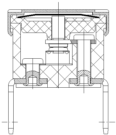
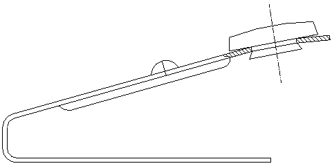
[0002] The jump-type thermostat used in the existing household appliances is mainly used for temperature control and overheating protection, etc. The thickness of the shrapnel used in the jump-type thermostat is generally between 0.1-0.3mm, such as figure 1 , 2 As shown, at present, the movable contact is riveted on the shrapnel by expanding the contact handle to make it interfere with the shrapnel hole. Due to the small thickness of the shrapnel, the conductive cross-sectional area of ​​this interference fit is very small, although the contact and the shrapnel There is a plane contact, but when the contact handle is expanded, this contact plane will be lifted, resulting in poor contact, so this riveting method is not suitable for household appliances with large current

Method used


Image

  • High-power kick type temperature controller and assembly method thereof
  • High-power kick type temperature controller and assembly method thereof
  • High-power kick type temperature controller and assembly method thereof

Examples


Embodiment 1

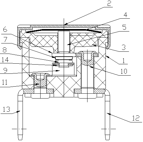
[0022] Such as image 3 , 4 , 5, the jump-type thermostat of this embodiment includes a housing 1, a cover 2, a guide frame 3, a bimetal disc 4, an action rod 5, a fixed plate 6, and a static contact 7. The static contact piece, the movable contact assembly composed of the movable contact 8 and the shrapnel 9, the first rivet 10, the second rivet 11, the first terminal 12, the second terminal 13, the action rod 5 is installed on the guide frame 3, the end of the action rod 5 faces the shrapnel 9; the bimetal disc 4 is located between the cover 2 and the action rod 5; On the inner and outer sides of the housing 1 , the elastic piece 9 and the second connection terminal 13 in the movable contact assembly are pressed against the inner and outer sides of the housing 1 by the second rivets 11 .

[0023] The above-mentioned assembly method of the jump-type thermostat includes the steps of assembling the movable contact assembly, installing the static contact piece and the first te...

Embodiment 2

[0028] Such as Image 6 As shown, the shrapnel 9 in this embodiment is provided with a nail hole, the handle of the movable contact 8 is a hollow handle, and the handle of the movable contact 8 is riveted with the shrapnel 9 after passing through the nail hole. The shank of 8 forms an annular pressing surface that is pressed against the shrapnel 9 .

[0029] The above steps of assembling the moving contact assembly are as follows: use the moving contact 8 with a hollow handle, pass the handle of the moving contact 8 through the nail hole and rivet it with the shrapnel 9, so that the handle of the moving contact 8 expands and flangs, and then connects with the The nail hole of the elastic piece 9 is interference fit, and makes the handle of the movable contact 8 form an annular pressing surface pressed against the elastic piece 9 .

[0030] Other structures and assembly methods of this embodiment are the same as those of Embodiment 1, and will not be repeated here.

[0031] ...

Embodiment 3

[0033] Such as Figure 7 As shown, the shrapnel 9 in this embodiment is provided with a nail hole, and the handle of the movable contact 8 is provided with an axial groove, and the handle of the movable contact 8 passes through the nail hole and is riveted with the shrapnel 9. The flanging of the handle of the contact 8 forms a pressing surface that is pressed against the elastic piece 9 .

[0034] The above steps of assembling the moving contact assembly are as follows: use the moving contact 8 with an axial groove on the handle, pass the handle of the moving contact 8 through the nail hole and rivet it with the shrapnel 9, so that the handle of the moving contact 8 expands Afterwards, the two sides are separated, and are interference-fitted with the nail holes of the elastic piece 9 , and the handle of the movable contact 8 forms a pressing surface pressed against the elastic piece 9 .

[0035] Other structures and assembly methods of this embodiment are the same as those o...


PUM


Abstract

The invention aims to provide a high-power kick type temperature controller and an assembly method thereof to improve the reliability of electric connection of an elastic piece and a movable contact so that the high-power kick type temperature controller can adapt to the large current work environment. The high-power kick type temperature controller comprises a shell, a closing cover, a guide frame, double metal discs, an acting rod, a static wafer composed of a fixed connection plate and a stationary contact, a movable contact assembly composed of the movable contact and the elastic piece, a first rivet, a second rivet, a first wiring terminal and a second wiring terminal. The high-power kick type temperature controller is characterized in that the elastic piece is provided with a nail hole, the handle portion of the movable contact penetrates through the nail hole to be riveted to the elastic piece, and a pressing surface pressing the elastic piece is arranged or formed at the handle portion of the movable contact. Through different matching structures of the handle portion of the movable contact and the elastic piece, the reliability of electric connection of the elastic piece and the movable contact is improved, and therefore the high-power kick type temperature controller can be applied to the large current or high power work environment, the work of the high-power kick type temperature controller is more reliable, and the service life of the high-power kick type temperature controller is prolonged at the same time.

Description

technical field [0001] The invention belongs to the technical field of home appliances, and in particular relates to a high-power snap-type thermostat and an assembly method thereof. Background technique [0002] The jump-type thermostat used in the existing household appliances is mainly used for temperature control and overheating protection, etc. The thickness of the shrapnel used in the jump-type thermostat is generally between 0.1-0.3mm, such as figure 1 , 2 As shown, at present, the movable contact is riveted on the shrapnel by expanding the contact handle to make it interfere with the shrapnel hole. Due to the small thickness of the shrapnel, the conductive cross-sectional area of ​​this interference fit is very small, although the contact and the shrapnel There is a plane contact, but when the contact handle is expanded, this contact plane will be lifted, resulting in poor contact, so this riveting method is not suitable for household appliances with large currents....

Claims


Application Information

Patent Timeline
Patent Type & Authority Applications(China)
IPC IPC(8): H01H37/52H01H11/00
Inventor 梁其章
Owner GUANGDONG FUER ELECTRONICS
Learn More