
High-speed electroplating rotary hull cell

A high-speed electroplating and Hull cell technology, applied in the field of Hull cell, can solve the problems of high debugging cost, single and complex plating solution information, etc.

Inactive Publication Date: 2014-10-01
HARBIN INST OF TECH
View PDF6 Cites 4 Cited by
  • Summary
  • Abstract
  • Description
  • Claims
  • Application Information

AI Technical Summary

Problems solved by technology

At present, there are very few tools directly used for high-speed electroplating research. In addition to high-speed jets, bubbling and other plating tanks that accelerate convective mass transfer of solutions, the analysis of high-speed plating solution performance also uses rotating cylindrical electrodes to analyze data, but the obtained plating solution information Single, it is more complicated to inspect or screen certain additives, and the cost of debugging on pilot equipment is relatively high

Method used


Image

  • High-speed electroplating rotary hull cell
  • High-speed electroplating rotary hull cell
  • High-speed electroplating rotary hull cell

Examples


Embodiment 1

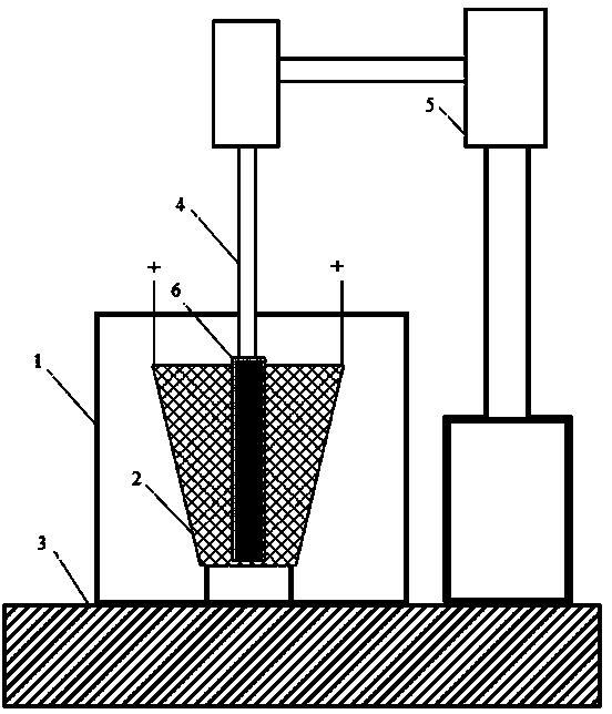
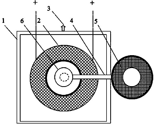
[0022] This embodiment provides a high-speed electroplating rotating Hull cell, which is composed of an electroplating cell body 1, a base 3, a mesh anode 2, a rotating cathode 6, a variable speed motor 5 and a cantilever 4 that drive the rotating electrode 6 to rotate. The bracket 1 is fixed on the bottom of the electroplating tank body 1, a mesh anode 2 is fixed on the electroplating tank body 1, and the rotating cathode 6 is inserted into the inside of the mesh anode 2. The rotating cathode 6 is connected with the swing arm 4, and the other end of the swing arm 4 is connected with a Variable speed motor 5, variable speed motor 5 is fixed outside electroplating tank body 1 with support 1.

[0023] Electroplating tank 1: the material is plexiglass, the shape is square, and the size is 140mm×140mm×60mm.

[0024] Mesh anode 2: the material is titanium-based iridium dioxide anode; diamond-shaped mesh, the overall shape is a circular truncated structure with a narrow lower end an...

Embodiment 2

[0064] The difference between this embodiment and the embodiment is: the material of the electroplating tank body 1 is PVC; the material of the mesh anode 2 is platinum with square mesh; the material of the rotating cathode 6 is copper pillar.

Embodiment 3

[0066] The difference between this embodiment and the embodiment is: the material of the electroplating tank body 1 is ceramics; the material of the mesh anode 2 is graphite with circular mesh; the material of the rotating cathode 6 is aluminum alloy.


PUM

PropertyMeasurementUnit
Lower mouth diameteraaaaaaaaaa
Upper mouth diameteraaaaaaaaaa
Heightaaaaaaaaaa

Abstract

A high-speed electroplating rotary hull cell relates to a hull cell and aims to achieve the purpose of researching the performance of a high-speed electroplating solution in labs. The hull cell consists of an electroplating bath body, a bracket, a reticular anode and a rotary cathode, as well as a variable speed motor and a cantilever which drive the rotary cathode to rotate, wherein the electroplating bath body and the variable speed motor are fixed to the bracket; the reticular anode is fixed to the bottom of the electroplating bath body; the rotary cathode is inserted into the reticular anode and connected with the variable speed motor outside the electroplating bath body through the cantilever. The high-speed electroplating rotary hull cell can not only simply, conveniently and quickly analyze the properties of a plating solution and screen additives but also simulate the high-speed electroplating process to research the performance and the processing parameters of the high-speed electroplating solution so as to make up the shortcomings of labs in the prior art.

Description

technical field [0001] The invention relates to a Hull cell, in particular to a rotary Hull cell which can be used for simulating high-speed electroplating. Background technique [0002] High-speed electroplating refers to the electroplating process that uses a current density that is more than 10 times greater than that of general static electroplating. Its biggest feature is fast plating speed (plating speed>1μm / min). The commonly used Hull cell is a small trapezoidal cell that can only simulate a certain range of current density. The results obtained can explain the performance of the plating solution under a certain current density. At present, there are very few tools directly used for high-speed electroplating research. In addition to high-speed jets, bubbling and other plating tanks that accelerate convective mass transfer of solutions, the analysis of high-speed plating solution performance also uses rotating cylindrical electrodes to analyze data, but the obtaine...

Claims


Application Information

Patent Timeline
IPC IPC(8): C25D17/02
Inventor 李宁王熙禹王志登黎德育王洺浩
Owner HARBIN INST OF TECH
Learn More