
How the transmission device works

A technology of conveying equipment and conveyor belts, applied in the direction of conveyors, conveyor objects, transportation and packaging, etc., to avoid tension, gently accelerate or decelerate, and eliminate rebound

Active Publication Date: 2016-08-17
SIEMENS AG
View PDF4 Cites 0 Cited by
  • Summary
  • Abstract
  • Description
  • Claims
  • Application Information

AI Technical Summary

Problems solved by technology

But this also achieved only a slight improvement

Method used


Image

  • How the transmission device works
  • How the transmission device works
  • How the transmission device works

Examples


Embodiment Construction

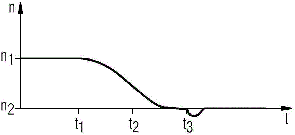
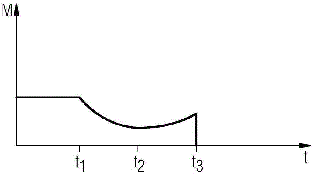
[0024] figure 1 A transport device 2 is shown with a conveyor belt 4 and a total of four drive rollers 6 for driving the conveyor belt 4 . In order for the conveyor belt 4 to rest against the drive pulley 6 in a corresponding range, the transport device 2 comprises a plurality of deflection pulleys 8 . In order to achieve a sufficient tension of the conveyor belt 4 also at different temperatures and loads, a tensioning carriage 10 is arranged along the conveyor belt 4 which can be driven in such a way that sufficient tension of the conveyor belt 4 is obtained. For example, in FIG. 2 a motor 12 is indicated on the drive drum 6 , which is connected to a frequency converter 14 with a control unit 16 . The drive roller is rotated by the motor 12 so that the drive roller exerts a force on the conveyor belt 4 . Therefore, the conveyor belt 4 itself rotates at a predetermined speed v in the direction indicated by the arrow in the running state. The speed v is set according to the ...


PUM


Abstract

The invention relates to a method for operating a conveyor belt (2) with a conveyor belt (4) and at least one drive roller (6) for driving the conveyor belt (4), wherein for changing the conveyor belt ( 4) at a speed controlled to act on the Torque (M) to drive the pulley (6).

Description

technical field [0001] The invention relates to a method for operating a conveyor with a conveyor belt and at least one drive roller for driving the conveyor belt. Background technique [0002] A conveying device, such as a trough conveyor or a tubular material conveyor, comprises a conveyor belt for conveying the conveyed product and at least one drive roller, by means of which the conveyor belt can be driven. The conveyor also has deflection rollers and a drive system for driving the drive rollers. The drive system includes a transmission and a motor. One or more frequency converters are used for driving and controlling the motor or motors, especially in the case of long conveyor belts. [0003] If the speed of the conveyor belt should be changed, e.g. at the start and stop of conveyor equipment, the objective exists to bring the conveyor belt from one speed level to another with as little strain as possible, i.e. decelerating or accelerating the drive pulley from a firs...

Claims


Application Information

Patent Timeline
Patent Type & Authority Patents(China)
IPC IPC(8): B65G43/00
CPCB65G43/00B65G23/04B65G15/30
Inventor 渥尔夫-马丁·拉森纳克
Owner SIEMENS AG
Learn More