Broadband resonant type wireless electric energy transmission system

A resonant radio and transmission system technology, applied in electromagnetic wave systems, electrical components, circuit devices, etc., can solve problems such as single frequency and insufficient frequency range

Active Publication Date: 2014-09-24
INST OF ELECTRICAL ENG CHINESE ACAD OF SCI
View PDF6 Cites 6 Cited by
  • Summary
  • Abstract
  • Description
  • Claims
  • Application Information

AI Technical Summary

Problems solved by technology

[0007] The purpose of the present invention is to overcome the shortcomings of single frequency or insufficient frequency range in the prior art, and propose a broadband resonant wireless power transmission system

Method used


Image

  • Broadband resonant type wireless electric energy transmission system
  • Broadband resonant type wireless electric energy transmission system
  • Broadband resonant type wireless electric energy transmission system

Examples


Embodiment Construction

[0019] The present invention will be further described below in conjunction with the accompanying drawings and specific embodiments.

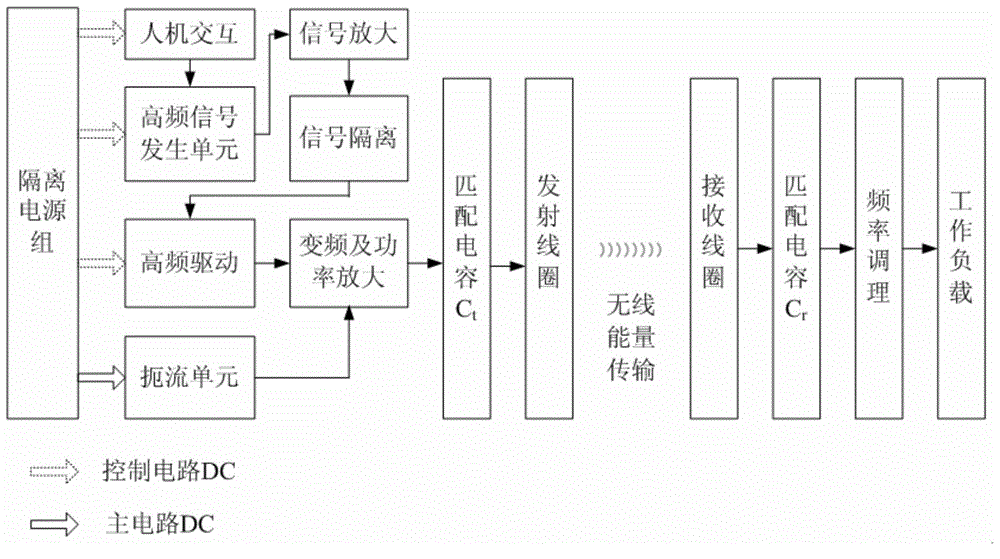
[0020] The invention performs wireless transmission of electric energy through a coupling resonance mode, adopts a single energy transmitting device to realize high-power transmission in a wide frequency range, and realizes high-efficiency energy transmission.

[0021] figure 1 Shown is a schematic block diagram of the broadband resonant wireless power transmission system of the present invention. The wireless power transmission system of the present invention includes an energy transmitting end and an energy receiving end. The energy transmitting end consists of an isolated power supply group, a human-computer interaction unit, a high-frequency signal generation unit, a signal amplification unit, a signal isolation unit, a high-frequency drive unit, a choke unit, a frequency conversion and power amplification unit, and a first matching capacit...


PUM


Abstract

A broadband resonant type wireless electric energy transmission system comprises an energy emission end and an energy receiving end. The energy emission end comprises an isolated power pack, a human-computer interaction unit, a high-frequency signal generating unit, a signal amplification unit, a high frequency driving unit, a choking unit, a frequency conversion and power amplification unit, a first matching capacitor and an emission coil, wherein a resonant emission circuit is composed of the first matching capacitor and the emission coil. The energy receiving end comprises a receiving coil, a second matching capacitor, a frequency regulator and a working load, wherein a resonant receiving circuit is composed of the receiving coil and the second matching capacitor, and power is supplied to the working load through the frequency regulator.

Description

technical field [0001] The invention relates to a resonant wireless power transmission system. Background technique [0002] Wireless power transmission technology is a power transmission technology that supports load equipment to obtain power from a power source in a non-contact manner. Wireless power transmission technology can effectively overcome the problems of poor equipment movement flexibility, space occupation, contact sparks, exposed cables and cable joints, and wear and tear of moving contact surfaces in the line power supply mode, and improve the safety and reliability of the power supply system. performance and service life. It is especially suitable for safe power supply of mobile equipment, flammable and explosive environments, and underwater and oil and gas downhole equipment. It has great scientific significance and practical value for the development of electromagnetic theory and power supply and utilization methods. It has broad application prospects in ...

Claims


Application Information

Patent Timeline
Patent Type & Authority Applications(China)
IPC IPC(8): H02J17/00H02J50/12
Inventor 李艳红刘国强宋显锦张超张瑞华
Owner INST OF ELECTRICAL ENG CHINESE ACAD OF SCI
Why Eureka
Try Eureka