Magnetron sputtering device and sputtering cathode thereof

A cathode and sputtering technology, which is applied in the direction of sputtering plating, ion implantation plating, metal material coating process, etc., can solve the problems of poor resistance uniformity, affecting the uniformity of glass substrate surface resistance, and the influence of target atom attachment.

Active Publication Date: 2014-09-17
WGTECH JIANGXI
View PDF6 Cites 2 Cited by
  • Summary
  • Abstract
  • Description
  • Claims
  • Application Information

AI Technical Summary

Problems solved by technology

However, since the glass substrate is located at the anode, the ionized electrons will accelerate to the glass substrate
Due to the bombardment of electrons, the attachment of target atoms will be affected, and the attachment of target atoms on the surface of

Method used


Image

  • Magnetron sputtering device and sputtering cathode thereof
  • Magnetron sputtering device and sputtering cathode thereof
  • Magnetron sputtering device and sputtering cathode thereof

Examples


Embodiment Construction

[0019] In order to facilitate the understanding of the present invention, the present invention will be described more fully below with reference to the associated drawings. Preferred embodiments of the invention are shown in the accompanying drawings. However, the present invention can be embodied in many different forms and is not limited to the embodiments described herein. On the contrary, these embodiments are provided to make the understanding of the disclosure of the present invention more thorough and comprehensive.

[0020] It should be noted that when an element is referred to as being “fixed” to another element, it can be directly on the other element or there can also be an intervening element. When an element is referred to as being "connected to" another element, it can be directly connected to the other element or intervening elements may also be present.

[0021] Unless otherwise defined, all technical and scientific terms used herein have the same meaning as...


PUM


Abstract

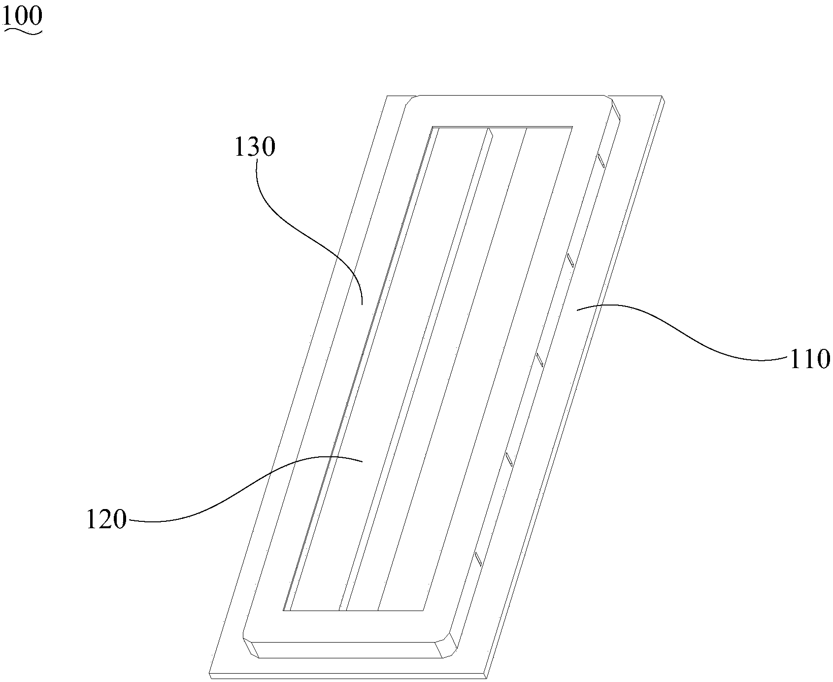
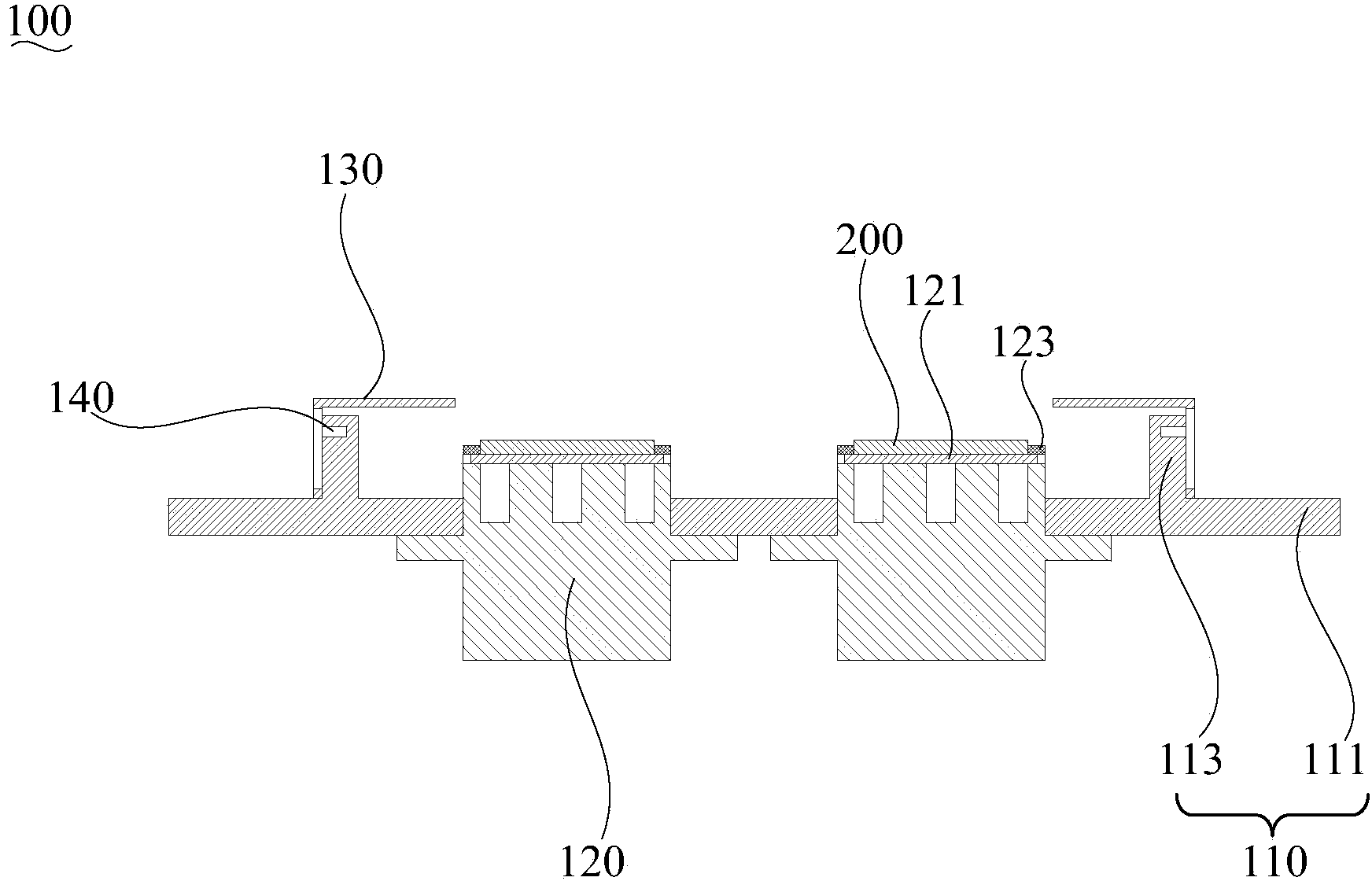
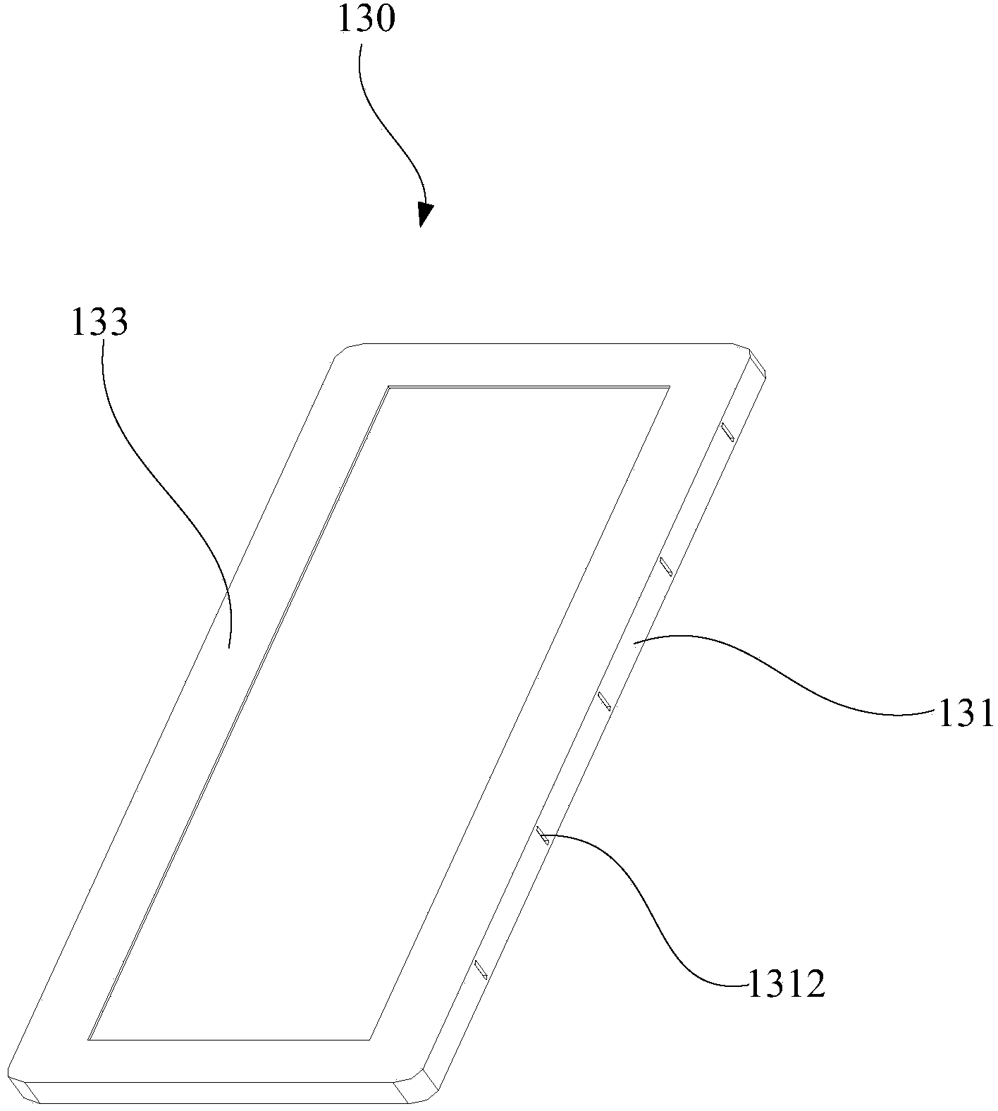
The invention discloses a magnetron sputtering device and a sputtering cathode thereof. The sputtering cathode comprises a cathode panel, a cathode and an anode cover, wherein the cathode panel and the cathode panel are insulated. For magnetron sputtering, the cathode is applied with a power negative electrode, and the cathode panel is relatively a positive electrode, and the anode cover is also connected with the cathode panel. Therefore, the anode cover is also a positive electrode relative to the target. After addition of the anode cover, ionized electrons fly to the anode cover, thereby reducing the bombardment of the electrons on the glass substrate to be coated, reducing the effect of electrons on the coating process, and further improving the uniformity of the film and the surface resistance.

Description

technical field [0001] The invention relates to material coating technology, in particular to a magnetron sputtering device and a sputtering cathode thereof. Background technique [0002] At present, when coating sheet materials such as glass substrates, magnetron sputtering coating is usually used. During the sputtering process, argon is used as the filling gas, and the argon is ionized by the electric field of the sputtering cathode to form argon ions and electrons. However, since the glass substrate is located at the anode, the ionized electrons will accelerate and fly to the glass substrate. Due to the bombardment of electrons, the attachment of target atoms will be affected, and the attachment of target atoms on the surface of the glass substrate will be uneven, which will affect the uniformity of the surface resistance of the glass substrate. Therefore, the coating film layer obtained by magnetron sputtering is unstable and has poor resistance uniformity, thereby aff...

Claims


Application Information

Patent Timeline
IPC IPC(8): C23C14/35
Inventor 张迅阳威欧阳小园易伟华
Owner WGTECH JIANGXI
Why Eureka
Try Eureka