
Method for manufacturing photoelectric composite medium-voltage drum cable

A process method and photoelectric composite technology, applied in the direction of cable/conductor manufacturing, circuit, electrical components, etc., can solve the problems of difficult control of conductive core and optical unit cabling, difficulty in guaranteeing optical fiber performance, long time, etc., to improve various Item performance and the effect of service life

Active Publication Date: 2014-09-10
JIANGSU HENGTONG POWER CABLE
View PDF4 Cites 12 Cited by
  • Summary
  • Abstract
  • Description
  • Claims
  • Application Information

AI Technical Summary

Problems solved by technology

In the photoelectric composite medium-voltage reel cable, the outer sheath of the optical unit is extruded with thermosetting rubber. Since the normal operating temperature of the optical fiber is -40°C-70°C, the temperature of the vulcanized tube when the rubber is extruded is 150°C- 200℃, the time is 10-20min, the temperature through the vulcanized tube is high, the time is long, it is difficult to guarantee the performance of the optical fiber; in addition, the conductive core and the optical unit in the cable are relatively difficult to control, which will also affect Service life of photoelectric composite medium voltage reel cable
In addition, the performance of the sheath material of the photoelectric composite medium-voltage reel cable is not too high, resulting in relatively poor tensile strength, low temperature resistance, and aging resistance of the cable.

Method used


Image

  • Method for manufacturing photoelectric composite medium-voltage drum cable
  • Method for manufacturing photoelectric composite medium-voltage drum cable
  • Method for manufacturing photoelectric composite medium-voltage drum cable

Examples


Embodiment

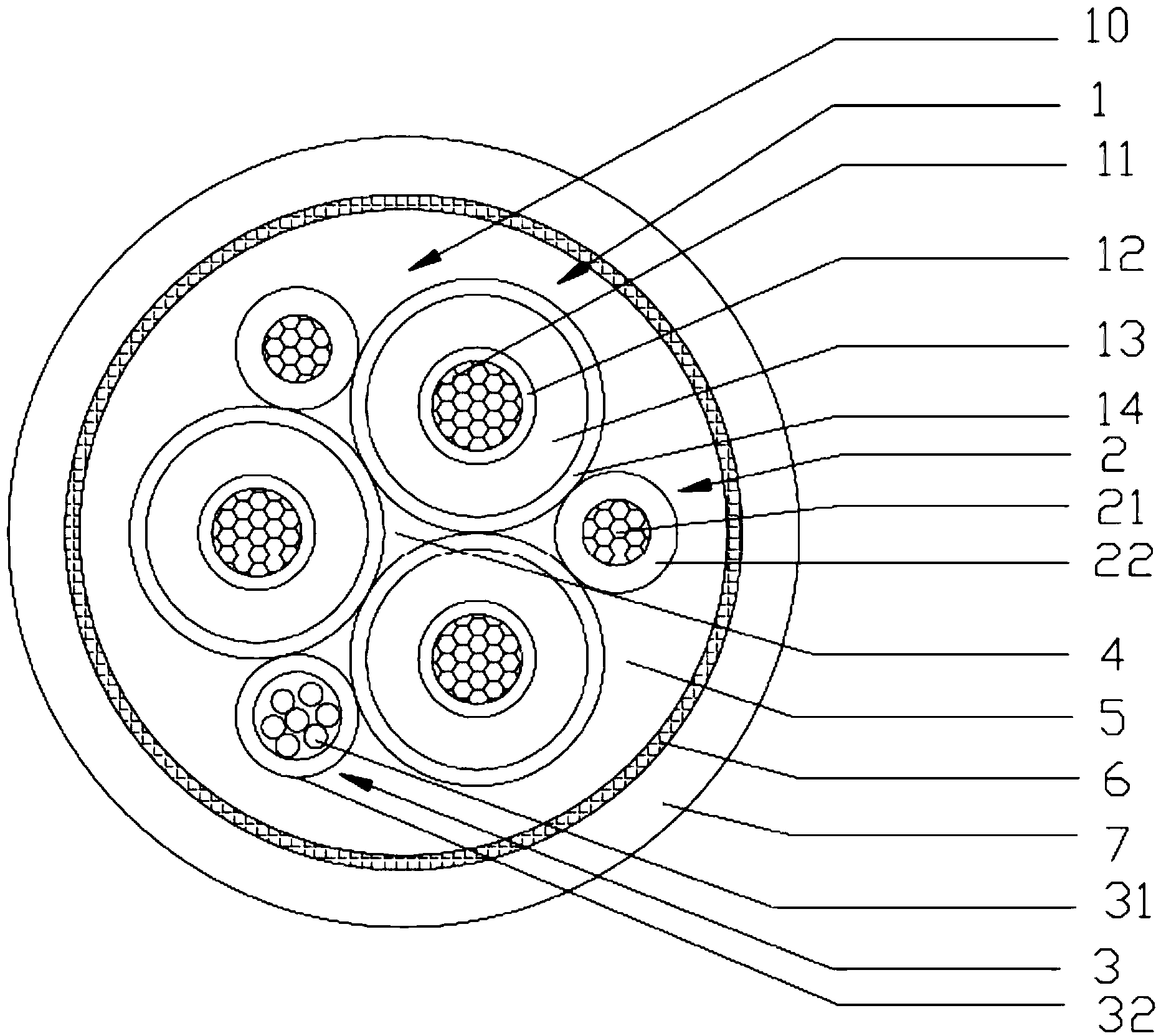
[0060] Example: see figure 1 As shown, a photoelectric composite medium-voltage reel cable with a rated voltage of 3.6 / 6kV-12 / 20kV, including three power cores 1 and two ground cores 2 twisted together to form a cable core 10, and an optical unit 3 , the special neoprene inner sheath 5 coated on the outside of the cable core 10, the reinforcement layer 6 braided on the outside of the special neoprene inner sheath 5 and embedded in it, the special neoprene coated on the outside of the reinforcement layer 6 The outer sheath 7 and the reinforcement layer 6 are formed by braiding high-strength polyester filaments. In the cable core 10, three power cores 1 are closely arranged along the circumferential direction, and the central gap between the three power cores 1 is filled with The semi-conductive filler 4, the semi-conductive filler 4 is made of semi-conductive rubber, the two ground wire cores 2 and a light unit 3 are scattered and arranged between the outer sides of two adjace...


PUM


Abstract

The invention discloses a method for manufacturing a photoelectric composite medium-voltage drum cable. The photoelectric composite medium-voltage drum cable comprises power line cores, ground line cores, at least one optical element, a special neoprene inner sheath wrapping a cable core, a reinforcing layer which is woven at the exterior of the special neoprene inner sheath and embedded in the special neoprene inner sheath and a special neoprene outer sheath wrapping the reinforcing layer; chlorinated polyethylene rubber materials include the following components of: a chlorinated polyethylene raw rubber, magnesium oxide, dibasic lead sulfate, lead sulfate tribasic, paraffin, chlorinated paraffin, antioxidant, namely, poly(1,2-dihydro-2,2,4-trimethyl-quinoline), a reinforcing agent (carbon black), flame retardant (antimony oxide), a filler (talcum powder), a filler (calcium carbonate), a reinforcing and filling agent (white carbon black), a vulcanizing promoter (triallyl isocyanurate), and a vulcanizing agent (dicumyl peroxide). With the method for manufacturing the photoelectric composite medium-voltage drum cable of the invention adopted, the cable can still keep excellent insulation performance under high temperature burning and humid conditions, and it can be ensured the cable can work normally for a long time under burning, mechanical percussion and water spraying situations.

Description

technical field [0001] The invention relates to a photoelectric composite medium-voltage reel cable, and also relates to a process for manufacturing a photoelectric composite medium-voltage reel cable. Background technique [0002] The existing photoelectric composite medium-voltage reel cable can be applied to applications with high mechanical stress, such as port machinery, such as shore container cranes, rail-mounted container gantry cranes, ship unloaders, stackers and reclaimers. and other heavy handling equipment. Photoelectric composite medium-voltage reel cable products are usually laid outdoors and are often used in harsh environmental conditions, such as: long-term sun and rain, day and night cold, frost and snow, corrosion by ultraviolet rays, ozone and other natural conditions, and performance decline Faster, shorter lifespan. During the use of the cable, the cable must withstand tensile, torsion and bending fatigue, resulting in a rapid decline in the performa...

Claims


Application Information

Patent Timeline
Patent Type & Authority Applications(China)
IPC IPC(8): H01B13/24H01B13/00
Inventor 王昆鲍继聪张新
Owner JIANGSU HENGTONG POWER CABLE
Learn More