
Spraying process for abrasion resistant layer of plunger contact surface

A contact surface and plunger technology, which is applied in the field of anti-abrasion layer spraying technology on the contact surface of the plunger, can solve the problems of low bonding strength, short service life, high porosity of the coating, etc., and achieve improved durability and wear resistance, effectively The protective effect and the effect of convenient processing

Inactive Publication Date: 2014-09-10
ZHEJIANG OUYAO MACHINERY
View PDF6 Cites 8 Cited by
  • Summary
  • Abstract
  • Description
  • Claims
  • Application Information

AI Technical Summary

Problems solved by technology

[0004] The key component of the plunger pump is the plunger. The airtightness of the plunger directly leads to the stability of the working pressure and flow of the pump. There are many kinds of plungers on the market, such as a ceramic with the patent number 200810112524.4 Plunger, this kind of plunger is made of ceramic material. The ceramic plunger has poor wear resistance, is relatively brittle, easy to break, and has a short service life. The wear-resistant layer is sprayed on the stopper rod. The interior of the traditional thermal spray coating is a layered superposition structure. The interface between the coating and the substrate interface and the internal structure of the coating are mechanically combined. The shortcomings of low bonding strength and easy peeling failure seriously affect the protective performance of the coating and the service life of the coating; in addition, the coating has high porosity and many cracks, which will accelerate the local corrosion of the coating, making the coating The corrosion resistance of the layer is very poor

Method used


Image

  • Spraying process for abrasion resistant layer of plunger contact surface

Examples


Embodiment 1

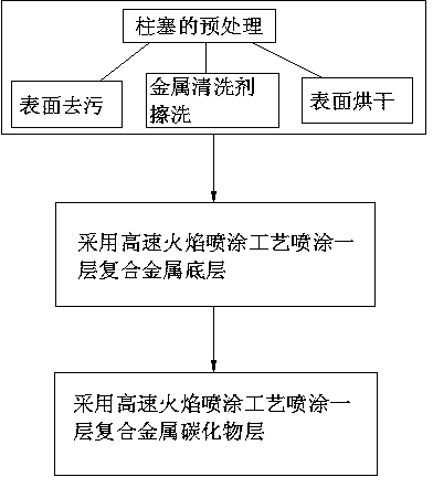
[0022] Embodiment 1: (a), the pretreatment of plunger: firstly adopt the heating method of 180 ℃ to remove all kinds of oil stains on the surface of the plunger, and then mix the metal cleaning agent with the warm water of 65 ℃ in a clean container, Wipe the plunger with a fine flat cloth and wipe it clean twice, then use water abrasive paper to polish the surface of the plunger evenly, and wipe the polished surface with a clean cloth; (b), spray the bottom layer: on the plunger The surface of the surface is sprayed with a layer of composite metal bottom layer by high-speed flame spraying process, (c), spraying protective layer, adopting a high-speed flame spraying process to spray a layer of composite metal carbide layer on the surface of the bottom layer; the spray gun used for spraying bottom layer ultra-high-speed flame spraying The jet flame speed is 1800m / s, the distance from the spray gun to the plunger surface is 15cm, the moving speed of the spray gun is 0.8m / s, the th...

Embodiment 2

[0023] Embodiment 2: (a), the pretreatment of plunger: firstly adopt the heating method of 190 ℃ to remove all kinds of oil stains on the surface of the plunger, and then mix the metal cleaning agent with the warm water of 68 ℃ in a clean container, Wipe the plunger with a fine flat cloth and wipe it clean twice, then use water abrasive paper to polish the surface of the plunger evenly, and wipe the polished surface with a clean cloth; (b), spray the bottom layer: on the plunger The surface of the surface is sprayed with a layer of composite metal bottom layer by high-speed flame spraying process, (c), spraying protective layer, adopting a high-speed flame spraying process to spray a layer of composite metal carbide layer on the surface of the bottom layer; the spray gun used for spraying bottom layer ultra-high-speed flame spraying The jet flame speed is 1900m / s, the distance from the spray gun to the plunger surface is 17cm, the moving speed of the spray gun is 1.0m / s, the th...

Embodiment 3

[0024]Embodiment 3: (a), the pretreatment of plunger: firstly adopt the heating method of 200 ℃ to remove all kinds of oil stains on the surface of the plunger, and then mix the metal cleaning agent with 70 ℃ warm water in a clean container, Wipe the plunger with a fine flat cloth and wipe it clean for 3 times, then polish the surface of the plunger evenly with a water abrasive paper, and wipe the polished surface with a clean cloth; (b), spray the bottom layer: on the plunger The surface of the surface is sprayed with a layer of composite metal bottom layer by high-speed flame spraying process, (c), spraying protective layer, adopting a high-speed flame spraying process to spray a layer of composite metal carbide layer on the surface of the bottom layer; the spray gun used for spraying bottom layer ultra-high-speed flame spraying The jet flame speed is: 2000m / s, the distance from the spray gun to the plunger surface is 20cm, the moving speed of the spray gun is 1.3m / s, the thi...


PUM

PropertyMeasurementUnit
Thicknessaaaaaaaaaa

Abstract

The invention discloses a spraying process for an abrasion resistant layer of a plunger contact surface, and relates to the technical field of abrasion resistance of a plunger pump. The spraying process comprises the following steps: various oil stain pollutants on the surface of a plunger are removed through baking for 3 hours in an oven; metal cleaner is mixed with warm water at a temperature of 68 DEG C in a clean container; the plunger is scrubbed and cleaned by wetting a broad cloth; the surface of the plunger is evenly polished by wetting a piece of waterproof abrasive paper; the polished surface is scrubbed for cleaning by using a clean cloth, and is dried in the oven; a composite metal bottom layer is sprayed on the surface of the plunger through a high-speed flame spraying process; and a composite metal carbide layer is sprayed on the surface of the bottom layer by the high-speed flame spraying process. The spraying process is simple, largely improves the durability and abrasion resistance of the plunger, enhances the stability of the plunger pump, and reduces the production cost; and the ultrahigh-speed spraying process is adopted, so that the carbide element oxidation burning loss is small, and the effective protection effect on the plunger is acted.

Description

technical field [0001] The invention relates to a process for spraying an anti-abrasion layer on a plunger contact surface, and belongs to the field of anti-abrasion technology of plunger pumps. Background technique [0002] The plunger pump is an important device in the hydraulic system. It relies on the reciprocating movement of the plunger in the cylinder to change the volume of the sealed working chamber to realize oil absorption and oil pressure. The plunger pump has the advantages of high rated pressure, compact structure, high efficiency and convenient flow adjustment, and is widely used in high pressure, large flow and flow adjustment occasions, such as hydraulic presses, engineering machinery and ships. [0003] When the plunger pump is working, the plunger reciprocates up and down, and the space above the plunger (pump cavity) generates a vacuum, thereby completing the oil pumping task. The plunger pump is introduced based on the principle of a plunger. There are...

Claims


Application Information

Patent Timeline
IPC IPC(8): C23C4/12C23C4/06C23C4/10C23C4/129
Inventor 钟新富胡宝林
Owner ZHEJIANG OUYAO MACHINERY
Learn More