Electromagnetic swirling continuous casting method
An electromagnetic and swirling device technology, applied in casting equipment, casting molten material containers, manufacturing tools, etc., to achieve the effects of saving refractory materials, simple equipment, and easy operation of equipment
- Summary
- Abstract
- Description
- Claims
- Application Information
AI Technical Summary
Problems solved by technology
Method used
Image


Examples
Embodiment 1
[0039] The electromagnetic swirl device used is horseshoe-shaped, with a structure such as Figure 7 shown;
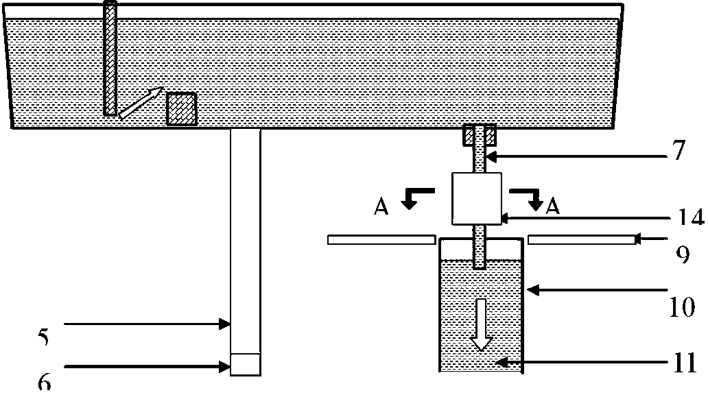
[0040] The electromagnetic swirling device is fixed on the moving device; the nozzle is a submerged nozzle between the tundish and the crystallizer; the moving device is a sliding wheel mechanism fixed on the tundish trolley;
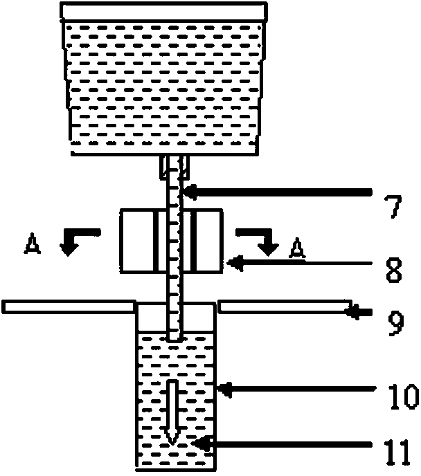
[0041] During continuous casting, the electromagnetic swirling device is moved around the nozzle through the moving device, and a rotating electromagnetic field is applied to the molten steel in the nozzle to rotate the molten steel in the nozzle to obtain a uniform outlet flow;
[0042] The electromagnetic swirl device is directly moved around the nozzle through the mobile device, so that the electromagnetic swirl device surrounds the nozzle; the working process is as follows: Figure 9 shown;
[0043] The electromagnetic swirl device is equipped with a water cooling jacket; the magnetic induction of the electromagnetic swirl device is at 10 ...
Embodiment 2
[0047] The electromagnetic swirl device used is a split 360° ring type, with a structure such as Figure 5 As shown; the split 360° ring type electromagnetic swirl device is divided into the first part and the second part, one end between the two parts is hinged, and the other end is equipped with a matching locking device;
[0048] The electromagnetic swirling device is fixed on the moving device; the nozzle is a submerged nozzle between the tundish and the crystallizer; the moving device is a sliding wheel mechanism fixed on the mobile trolley;
[0049] During continuous casting, the electromagnetic swirling device is moved around the nozzle through the moving device, and a rotating electromagnetic field is applied to the molten steel in the nozzle to rotate the molten steel in the nozzle to obtain a uniform outlet flow;
[0050] When the electromagnetic swirling device is in the standby position, open the locking device of the electromagnetic swirling device; when it is nec...
Embodiment 3
[0054] The electromagnetic swirl device used is a 180o semi-circular ring type, with a structure such as Figure 6 shown;
[0055] The electromagnetic swirling device is fixed on the moving device; the nozzle is a long nozzle between the ladle and the tundish; the moving device is a sliding wheel mechanism fixed on the mobile trolley;
[0056] During continuous casting, the electromagnetic swirling device is moved around the nozzle through the moving device, and a rotating electromagnetic field is applied to the molten steel in the nozzle to rotate the molten steel in the nozzle to obtain a uniform outlet flow;
[0057] The electromagnetic swirl device is equipped with an air-cooled sleeve; the magnetic induction of the electromagnetic swirl device is at 10 -1 T, frequency at 50Hz;
[0058] The sliding wheel mechanism includes a cantilever, a pulley and a bracket; the electromagnetic swirl device is fixed on the bracket, the bracket is fixed on the pulley, and the pulley is ...
PUM
 Abstract
Description
Claims
Application Information
 - R&D
- Intellectual Property
- Life Sciences
- Materials
- Tech Scout
- Unparalleled Data Quality
- Higher Quality Content
- 60% Fewer Hallucinations
Browse by: Latest US Patents, China's latest patents, Technical Efficacy Thesaurus, Application Domain, Technology Topic, Popular Technical Reports.
© 2025 PatSnap. All rights reserved.Legal|Privacy policy|Modern Slavery Act Transparency Statement|Sitemap|About US| Contact US: help@patsnap.com