
Sputtering target and process for producing same

A manufacturing method and sputtering target technology, applied in the field of sputtering targets, can solve problems such as abnormal discharge, generation of spots, increase of abnormal discharge, etc., achieve high mass productivity, suppress moisture absorption and discoloration, and suppress abnormal discharge effects

Active Publication Date: 2014-09-03
MITSUBISHI MATERIALS CORP
View PDF8 Cites 3 Cited by
  • Summary
  • Abstract
  • Description
  • Claims
  • Application Information

AI Technical Summary

Problems solved by technology

That is, Na compounds tend to adsorb moisture in the environment, and thus discoloration and spots often occur on the surface of the target, so there is a disadvantage that the characteristics of the solar cell finally manufactured from the target become extremely unstable
[0022] In addition, there are disadvantages such as increased abnormal discharge during sputtering due to the addition of a large amount of Na compound, lower mechanical strength, and easy cracking.
That is, there is a problem that the mechanical strength of the target decreases due to the addition of a large amount of Na compounds that are non-conductive, difficult to sinter, and have low mechanical strength, and the defect generation rate increases during machining, so that Na compounds are easily generated during sputtering. Abnormal discharge caused by

Method used


Image

  • Sputtering target and process for producing same
  • Sputtering target and process for producing same
  • Sputtering target and process for producing same

Examples


preparation example Construction

[0091]

[0092] In order to prepare the mixed powder of the Na compound powder and the Cu-Ga powder, it is possible to use a pulverizing and mixing device (for example, a ball mill, a jet mill, a Henschel mixer, an attritor, etc.) which differs in the pulverization method and the mixing method. The following methods (1) to (3).

[0093] (1) When crushing the Na compound powder and mixing with the Cu-Ga powder, respectively

[0094] It is preferable that the average secondary particle diameter of the Na compound obtained by crushing is 1-5 micrometers. The crushing process is preferably performed in a dry environment with humidity RH: 40% or less. As described above, the crushed Na compound powder thus obtained is preferably dried at 70°C or higher before mixing.

[0095] Next, using a dry mixer, the Na compound powder and the Cu—Ga powder prepared with the target composition were mixed in a dry environment with a relative humidity of RH: 40% or less to prepare a mixed powd...

Embodiment

[0124] Next, the evaluation results of the sputtering target and the manufacturing method thereof according to the present invention will be described with reference to the examples prepared according to the above-described embodiments.

[0125] "Example"

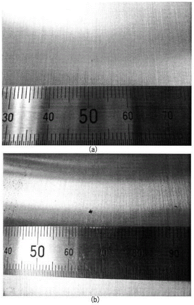
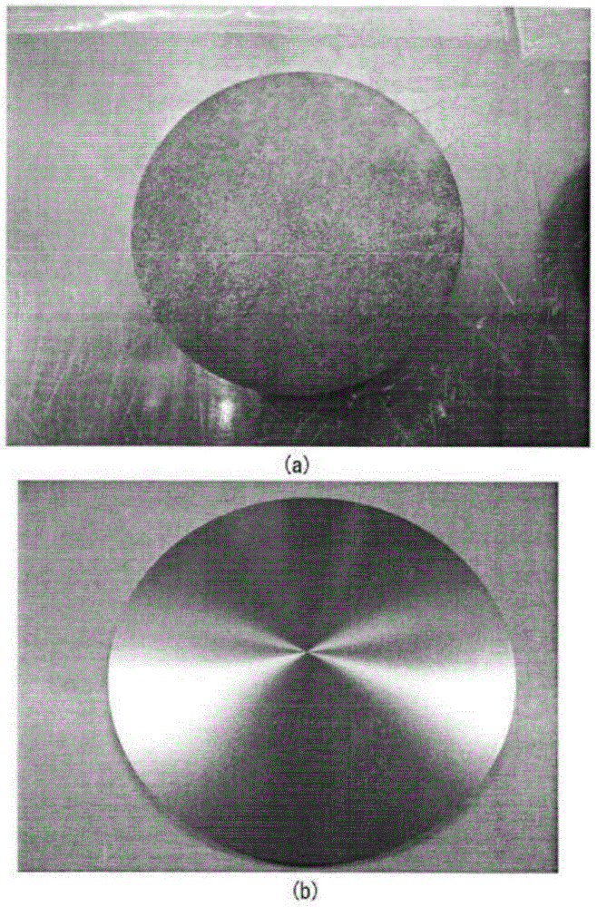
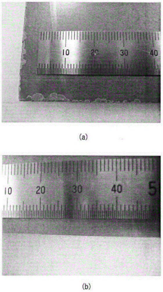
[0126] First, Cu—Ga alloy powder, Cu powder (purity 4N), and Na compound powder having a purity of 3N and a primary average particle size of 1 μm having the composition and particle size shown in Table 1 were blended into the composition shown in Table 1. amount to prepare mixed powders of Examples 1 to 24. These mixed powders were dried in the vacuum environment specified above. After that, the dried raw material powder was put into a polyethylene bottle with a volume of 10 L, and zirconia balls with a diameter of 2 mm which were dried at 80° C. for 10 hours were also put in, and mixed with a ball mill for a predetermined time. The mixing is carried out in a nitrogen atmosphere. In addition, the zirconia balls with a di...


PUM

PropertyMeasurementUnit
Flexural strengthaaaaaaaaaa
Particle sizeaaaaaaaaaa
Roughnessaaaaaaaaaa

Abstract

Provided is a sputtering target which contains Na in a high concentration and, despite this, is inhibited from discoloring, generating spots, and causing abnormal discharge and which has high strength and rarely breaks. Also provided is a process for producing the sputtering target. The sputtering target has a composition which contains 10-40 at% Ga and 1.0-15 at% Na as metallic components other than F, S, and Se, with the remainder comprising Cu and unavoidable impurities, the Na being contained in the form of at least one Na compound selected from sodium fluoride, sodium sulfide, and sodium selenide. The sputtering target has a theoretical density ratio of 90% or higher, a folding strength of 100 N / mm2 or higher, and a bulk resistivity of 1 mOmegacm or less. The number of 0.05 mm2 or larger aggregates of the at least one of sodium fluoride, sodium sulfide, and sodium selenide present per cm2 of the target surface is 1 or less on average.

Description

technical field [0001] The present invention relates to a sputtering target used for forming a Cu-In-Ga-Se compound film (hereinafter sometimes abbreviated as a CIGS film) for forming a light absorption layer of a thin-film solar cell, and a method for producing the same. Background technique [0002] In recent years, thin-film solar cells composed of chalcopyrite-based compound semiconductors have been put into practical use. The thin-film solar cells composed of the compound semiconductors have a basic structure in which Mo as a positive electrode is formed on a soda-lime glass substrate. The electrode layer has a light absorption layer made of a CIGS film formed on the Mo electrode layer, a buffer layer made of ZnS, CdS, etc. is formed on the light absorption layer, and a negative electrode is formed on the buffer layer. Transparent electrode layer. [0003] As a method of forming the above-mentioned light absorbing layer, a method of forming a film by a vapor deposition...

Claims


Application Information

Patent Timeline
IPC IPC(8): C23C14/34
CPCC22C1/0425C23C14/087B22F2201/20C23C14/3414C23C14/35C23C14/08H01J37/3429C22C32/0089B22F3/10B22F2301/00C23C14/0623B22F2999/00B22F3/1007
Inventor 张守斌梅本启太小路雅弘
Owner MITSUBISHI MATERIALS CORP
Learn More