Solar building roof

A solar building and roofing technology, applied in sustainable building, renewable energy integration, roofing using tile/slate tile, etc. High structural strength and good windproof effect

Inactive Publication Date: 2014-09-03
NANYANG INST OF TECH +4
View PDF8 Cites 6 Cited by
  • Summary
  • Abstract
  • Description
  • Claims
  • Application Information

AI Technical Summary

Problems solved by technology

However, the main problem of the current photovoltaic roof is that the photovoltaic panels and the roof of the building are independent of each other. When installing photovoltaic panels, it is necessary to first build a metal bracket on the roof of the brick or concrete structure, and then lay the photovoltaic panel components.
The disadvantages of this structure are: 1. The burden on the roof is so heavy that more parts of the roof cannot be built at all; 2. The windproof performance is very weak, and it is difficult to resist strong typhoons.
[0007] For the above-mentioned patent application, it can indeed reduce the load-bearing burden of the roof; however, the instructions do not record how to construct and install this type of photovoltaic module. From the perspective of its structural characteristics, the photovoltaic module still needs to be installed on the roof through bolts, etc. The connector fixes the photovoltaic module on the roof, otherwise, relying only on the friction fit between the bottom surface of the photovoltaic module and the roof tile surface, and the snap fit of the male and female frame of the adjacent photovoltaic module, it is impossible to withstand the attack of strong winds
On the other hand, for the vertically adjacent photovoltaic modules, the manual does not give a matching method, and it is difficult to deduce a suitable matching method according to the structure of the photovoltaic modules, so that the upper and lower adjacent photovoltaic modules Waterproof lap joints can be used between them, because photovoltaic panel components are much thicker than tiles. For adjacent photovoltaic panel components, they cannot be the same as tiles. Press the upper edge of the lower photovoltaic panel components against the upper photovoltaic panel components. It can be seen that for this type of photovoltaic panel assembly, there are actually obvious construction difficulties; in addition, this type of matching method that relies on the male and female frame buckles is easy to be damaged due to too late in rainy weather. Drainage makes the roof water overflow through the gap of the buckle, causing the roof to leak

Method used


Image

  • Solar building roof
  • Solar building roof
  • Solar building roof

Examples


Embodiment 1

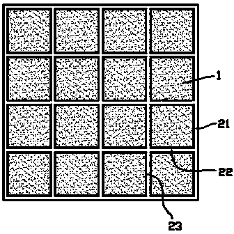
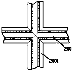
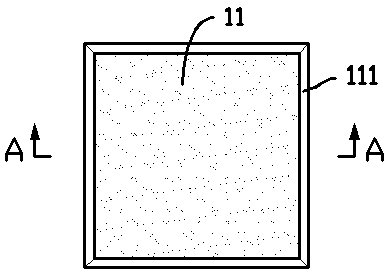
[0028] exist figure 1 In the shown embodiment one, the solar building roof includes a metal frame erected on the roof beams; the metal frame includes a rectangular frame 21 adapted to the size of the roof; the rectangular frame 21 is composed of beams 22 equidistantly distributed , and the equidistant longitudinal beams 23 are divided into a series of sash grids; the rectangular frame 21, cross beam 22, and longitudinal beam 23 are all formed of channel steel 200 with opening grooves upward, and the opening grooves of each channel steel 200 are mutually connected at the intersections. connected, such as figure 2 As shown, it can be connected by welding; rubber pads (not shown) are provided on the two upper edges of the opening grooves of each channel steel 200; the shape and size of each grid match a photovoltaic panel assembly 1; Said photovoltaic module 1 such as image 3 , 4 As shown, it includes a frame box 13 with an opening facing upwards. In the sealed cavity 10 in ...

Embodiment 2

[0037] For the second embodiment, the metal frame is set at a slanting position with the north high and the south low, so as to provide a good lighting angle; in this case, the difference from the first embodiment is:

[0038] Such as Figure 8 As shown, the crossbeam 22 and the longitudinal beam 23 are all relative to the center line of the upper edge and the lower edge of the rectangular frame 21 (ie Figure 8 a-a line) in the oblique distribution, and all the beams 22 and all the longitudinal beams 23 are symmetrical about the center line between the upper edge and the lower edge of the rectangular frame; this structure changes the pattern of the traditional horizontal arrangement of the upper and lower edges of the photovoltaic panel assembly, That is, the photovoltaic panel assembly is laid in an unconventional position, and the benefits obtained are: 1. The supporting edge of each sash for the photovoltaic panel assembly is changed from one to two, which improves the str...


PUM


Abstract

The invention provides a solar building roof which comprises a metal framework erected on roof beams. The framework comprises a rectangular, and the rectangular frame is divided into a serial of frame grids by horizontal beams and longitudinal beams. The rectangular frame, the horizontal beams and the longitudinal beams are all formed by steel channels with upward opening grooves, the opening grooves of the steel channels are communicated with each other at the intersection positions, rubber pads are arranged on two upper edges of the opening groove of each steel channel, and the shape and the size of each frame grid are matched with those of a photovoltaic panel assembly. Each photovoltaic panel assembly comprises a frame box with an upward opening, a photovoltaic wafer is laid in the frame box, the frame box is sealed by a glass cover plate, and the periphery of the frame box extends outwards to form an inclined downward cap brim. Two photovoltaic panel assemblies are embedded into two adjacent frame grids, a gap is reversed between the cap brims of the two photovoltaic panel assemblies, and a wiring box of each photovoltaic panel assembly is electrically connected with a charger and a storage battery. The roof can provide large-size lighting, is convenient to construct and high in structural strength and has excellent water draining and windproof effects.

Description

[0001] technical field [0002] The invention relates to the field of solar building facilities, in particular to a solar building roof. [0003] Background technique [0004] With the increasing global energy crisis, the concept of energy saving and environmental protection has been widely promoted; especially, the utilization of solar energy has become very popular. [0005] Among them, the concept of photovoltaic roofs has also begun to be widely implemented. However, the main problem of the current photovoltaic roof is that the photovoltaic panels and the roof of the building are independent of each other. When installing photovoltaic panels, it is necessary to first build a metal bracket on the roof of the brick or concrete structure, and then lay the photovoltaic panel components. The disadvantages of this structure are: 1. The burden on the roof is extremely heavy, so that more parts of the roof cannot be constructed at all; 2. The windproof performance is very weak...

Claims


Application Information

Patent Timeline
Patent Type & Authority Applications(China)
IPC IPC(8): E04D13/18H02S30/10H01L31/048H02S40/44H02S40/42
CPCY02B10/70Y02B10/12Y02E10/50Y02E10/60Y02B10/10
Inventor 马根昌
Owner NANYANG INST OF TECH
Why Eureka
Try Eureka