LED backlight driving circuit and liquid crystal display

A backlight drive circuit and LED light string technology, which is applied in static indicators, optics, instruments, etc., can solve the problems of drive circuit drive efficiency deterioration, achieve the goals of reducing drive frequency, lower power consumption, and improving drive efficiency Effect

Active Publication Date: 2014-08-27
TCL CHINA STAR OPTOELECTRONICS TECH CO LTD
View PDF7 Cites 30 Cited by
  • Summary
  • Abstract
  • Description
  • Claims
  • Application Information

AI Technical Summary

Problems solved by technology

However, as mentioned above, the driving frequency of the circuit is fixed, and the power consumption of the inductor L, the rectifier diode D1, and the first field effect transistor Q1 in the boost circuit are all proportional to Fs, therefore, in the When the duty ratio of the two square wave signal PWM2 decreases, the driving frequency Fs can be reduced accordingly but not actually reduced, and the driving efficiency of the driving circuit will be deteriorated.

Method used


Image

  • LED backlight driving circuit and liquid crystal display
  • LED backlight driving circuit and liquid crystal display
  • LED backlight driving circuit and liquid crystal display

Examples


Embodiment Construction

[0031] The present invention will be further described below with embodiments in conjunction with the accompanying drawings.

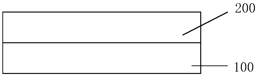
[0032] Such as figure 2As shown, this embodiment provides a liquid crystal panel 200 and a backlight module 100 that are arranged oppositely, and the backlight module 100 provides a display light source to the liquid crystal panel 200, so that the liquid crystal panel 200 displays images, wherein, The backlight module 100 adopts LED backlight.

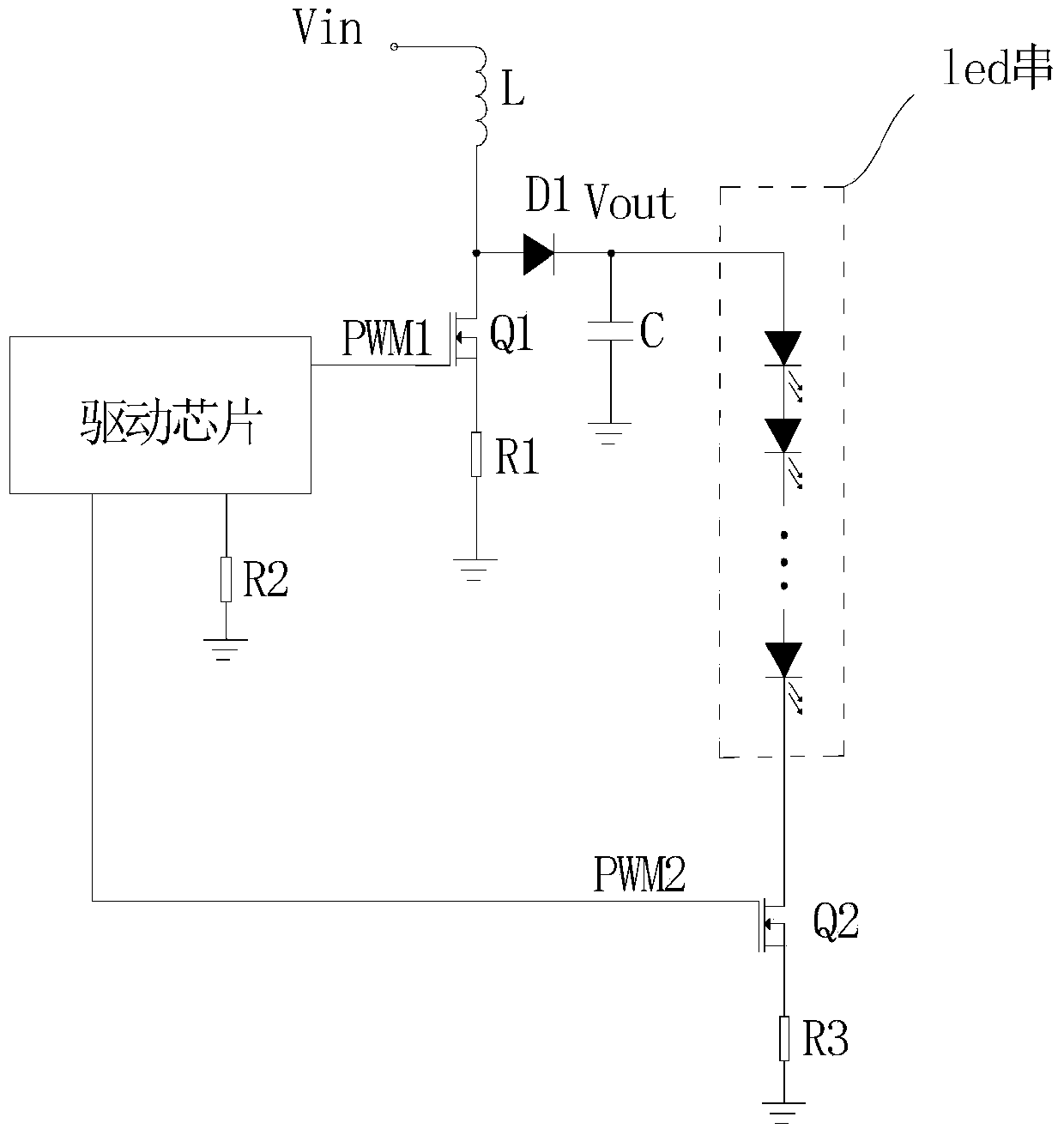
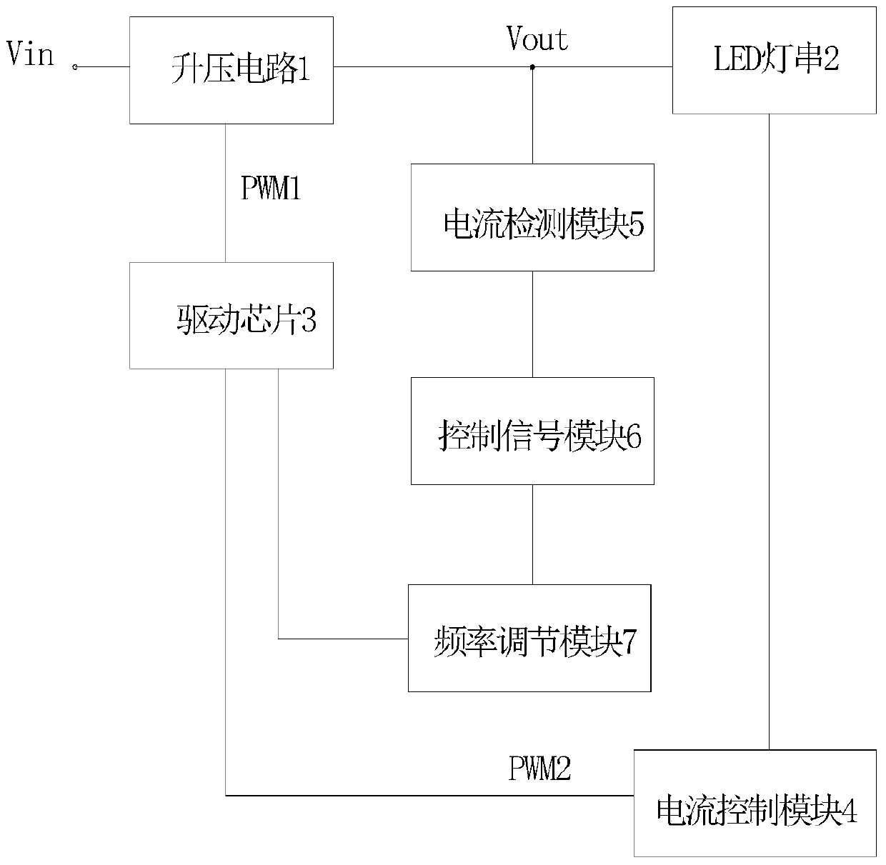
[0033] refer to Figure 3-7 , the driving circuit of the LED backlight is provided in this embodiment. image 3 Is the connection block diagram of the drive circuit. Such as image 3 As shown, the drive circuit includes: a booster circuit 1, which is used to convert the input voltage Vin into a required output voltage Vout and provide it to the LED light string 2; a current control module 4, connected to the negative terminal of the LED light string 2 , used to adjust the working current of the LED light ...


PUM


Abstract

The invention discloses an LED backlight driving circuit. The LED backlight driving circuit comprises a boosting circuit, a current control module, a driving chip, a current detection module, a control signal module and a frequency adjusting module, wherein the boosting circuit is used for converting an input voltage into a required output voltage and providing the output voltage for an LED string light, the current control module is connected to the negative end of the LED string light and used for adjusting the working current of the LED string light, the driving chip is used for providing a first square-wave signal for the boosting circuit and providing a second square-wave signal for the current control module, the current detection module is used for detecting the working current of the LED string light and generating a detection signal, the control signal module receives the detection signal generated by the current detection module and generates a control signal, the frequency adjusting module receives the control signal generated by the control signal module and generates a resistance value according to the control signal, the frequency adjusting module is further connected to the driving chip, and the driving chip adjusts the driving frequency of the backlight driving circuit according to the resistance value. The invention further discloses a liquid crystal display with the backlight driving circuit.

Description

technical field [0001] The invention relates to an LED backlight driving circuit, in particular to an LED backlight driving circuit capable of adjusting the driving frequency according to the magnitude of the working current, and a liquid crystal display provided with the LED backlight driving circuit. Background technique [0002] With the continuous advancement of technology, the backlight technology of liquid crystal display devices has been continuously developed. A backlight source of a traditional liquid crystal display device uses a cold cathode fluorescent lamp (CCFL). However, due to the shortcomings of CCFL backlight such as poor color reproduction ability, low luminous efficiency, high discharge voltage, poor discharge characteristics at low temperature, and long time for heating to reach a stable gray level, backlight technology using LED backlight has been developed. [0003] attached figure 1 It is a circuit diagram of an existing driving circuit for an LED b...

Claims


Application Information

Patent Timeline
Patent Type & Authority Applications(China)
IPC IPC(8): G09G3/34G09G3/36
CPCG09G3/3406G09G2320/064G09G2330/021H05B45/38Y02B20/30G09G2360/14G02F1/133612G09G3/36
Inventor 曹丹
Owner TCL CHINA STAR OPTOELECTRONICS TECH CO LTD
Why Eureka
Try Eureka