Welding transmission structure of partition plate of oil tank
A transmission structure and oil tank technology, applied in welding equipment, auxiliary welding equipment, welding/cutting auxiliary equipment, etc., can solve the problems of manual welding quality decline, increase production cost, increase material consumption, etc., to increase the fixing effect and improve efficiency , Guarantee the effect of welding effect
- Summary
- Abstract
- Description
- Claims
- Application Information
AI Technical Summary
Problems solved by technology
Method used
Image
Examples
Embodiment 1
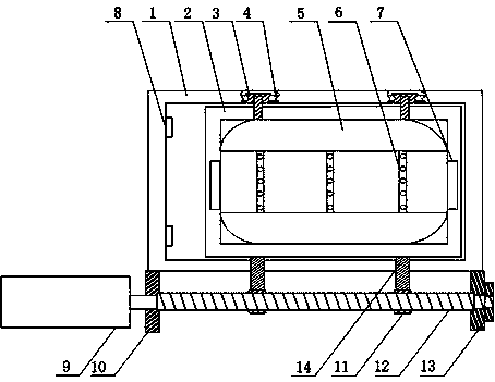
[0020] Such as figure 1 As shown, the oil tank 5 partition spot welding transmission tooling of the present invention includes an operating platform 1 and a clamping base 2, a guide rail 4 is arranged on the operating platform 1, and a roller 3 is installed on one side of the clamping base 2 , the roller 3 is slidingly arranged on the guide rail 4, and also includes a driving motor 9 and a bearing 13 installed on the side of the operating platform 1, the output end of the driving motor 9 is connected to a screw 12, and the screw 12 is rotated and arranged on the bearing 13 Inside, a connecting rod 14 is installed on the other side of the clamping base 2, and the end of the connecting rod 14 is provided with a nut 12, and the nut 12 is threadedly matched with the screw rod 12, and a travel switch is installed on the operating platform 1. 8, and the limit switch 8 is facing the end of the clamping base 2, and the limit switch 8 is connected with the driving motor 9 through a wir...
Embodiment 2
[0022] Such as figure 1 As shown, in this embodiment, on the basis of Embodiment 1, the upper surface of the clamping base 2 is a rounded rectangle matching the bottom of the fuel tank 5, and clamps 7 are installed at both ends of the clamping base 2 . Due to the shape limitation of the fuel tank 5, on the clamping base 2, the contact between the bottom of the fuel tank 5 and the flat upper surface of the clamping base 2 will cause the offset of the fuel tank 5, which will easily cause poor welding or wrong welding during the welding process. The upper surface of the holding base 2 is set as a rectangle with rounded corners, which can increase the fixing effect of the fuel tank 5, and the clamps 7 at both ends of the clamping base 2 can further reinforce the fuel tank 5, ensuring the stability and welding effect of the fuel tank 5 when welding the partition.
Embodiment 3
[0024] Such as figure 1 As shown, on the basis of Embodiment 1, this embodiment also includes a guide plate 10, the guide plate 10 is installed on the operating platform 1, a through hole is opened on the guide plate 10, and the output end of the drive motor 9 passes through the through hole. The hole is connected with the screw mandrel 12. During the welding process, the drive motor 9 needs to be constantly switched off, and when the drive motor 9 is started, the screw mandrel 12 connected to the output end of the drive motor 9 will inevitably feel frustrated, so that the screw mandrel 12 will shake radially. As a result, the welding head does not correspond to the welding spot 6 of the partition during welding. The guide plate 10 is installed on the operating platform 1, which can not only play a guiding role for the screw rod 12, but also eliminate the radial stress generated by the screw rod 12. Ensure the one-to-one correspondence between the welding spot 6 and the weldi...
PUM
 Abstract
Description
Claims
Application Information
 - R&D
- Intellectual Property
- Life Sciences
- Materials
- Tech Scout
- Unparalleled Data Quality
- Higher Quality Content
- 60% Fewer Hallucinations
Browse by: Latest US Patents, China's latest patents, Technical Efficacy Thesaurus, Application Domain, Technology Topic, Popular Technical Reports.
© 2025 PatSnap. All rights reserved.Legal|Privacy policy|Modern Slavery Act Transparency Statement|Sitemap|About US| Contact US: help@patsnap.com

