
Silicon carbide ceramic lined desulphurization pump

A technology for lining silicon carbide and desulfurization pumps, which is applied to pumps for special fluids, components of pumping devices for elastic fluids, pumps, etc., which can solve the problem of reduced sealing performance at plane joints, short service life, and increased difficulty. and other problems to achieve the effect of ensuring shape and dimensional accuracy, prolonging service life and improving service life

Active Publication Date: 2014-08-13
SHENYANG FIRST PUMP CO LTD
View PDF7 Cites 15 Cited by
  • Summary
  • Abstract
  • Description
  • Claims
  • Application Information

AI Technical Summary

Problems solved by technology

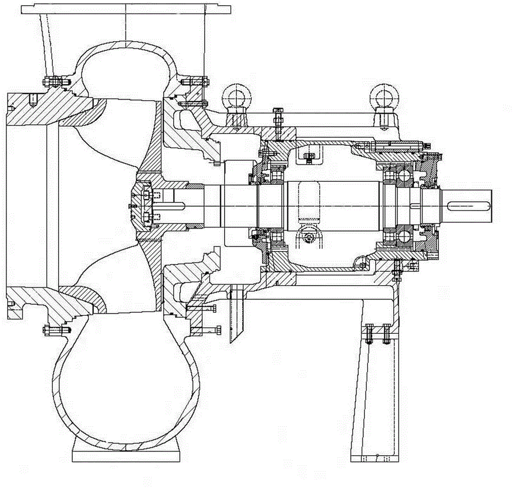
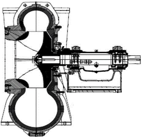
However, the German Duechting pump body structure is radially split, which increases the difficulty of plane processing; moreover, the sealing performance of the plane joint is reduced, and its structure is shown in the appendix figure 2
[0012] (3) The desulfurization pump of WARMAN in Australia is lined with rubber, which is limited by the inherent properties of rubber, and has a short lifespan, colloids are easy to fall off, and colloid particles are easy to block nozzles, etc.
Since the ceramic lining is processed first, and then the ceramic lining is embedded into the metal shell of the pump body, the flow passages of the pumps with these two structures can only be made into a regular ring shape, and the external dimensions of the pump cannot be made too large. , resulting in limited range of performance, the flow rate is only 400m 3 / h, and the efficiency of the pump is lower than that of the normal pump

Method used


Image

  • Silicon carbide ceramic lined desulphurization pump
  • Silicon carbide ceramic lined desulphurization pump
  • Silicon carbide ceramic lined desulphurization pump

Examples


Embodiment

[0086] Example: The specific manufacturing process of the ceramic desulfurization pump (ACP-TL700-22).

[0087] (1) Determine the suction diameter and discharge diameter: suction diameter = 800mm, discharge diameter = 700mm, determine the rotational speed as 595r / min, and the specific rotational speed of the pump = 330.4. Determine the structural form as a single-stage, single-suction volute structural form.

[0088] (2) Determine the geometric size of the impeller according to the performance and parameters: inlet diameter D 0 =Φ690, outlet width b 2 =220, outer diameter D2=Φ865, blade wrap angle ψ=115°. The number of blades is 5, and the hydraulic diagram and processing diagram of the impeller are drawn according to the calculation parameters.

[0089] (3) Determine the design of the spiral vortex chamber: base circle diameter D 3 =Φ918, vortex chamber inlet width b 3 =320.

[0090] Determination of the area of ​​the end face of the vortex chamber: the size of the end ...


PUM


Abstract

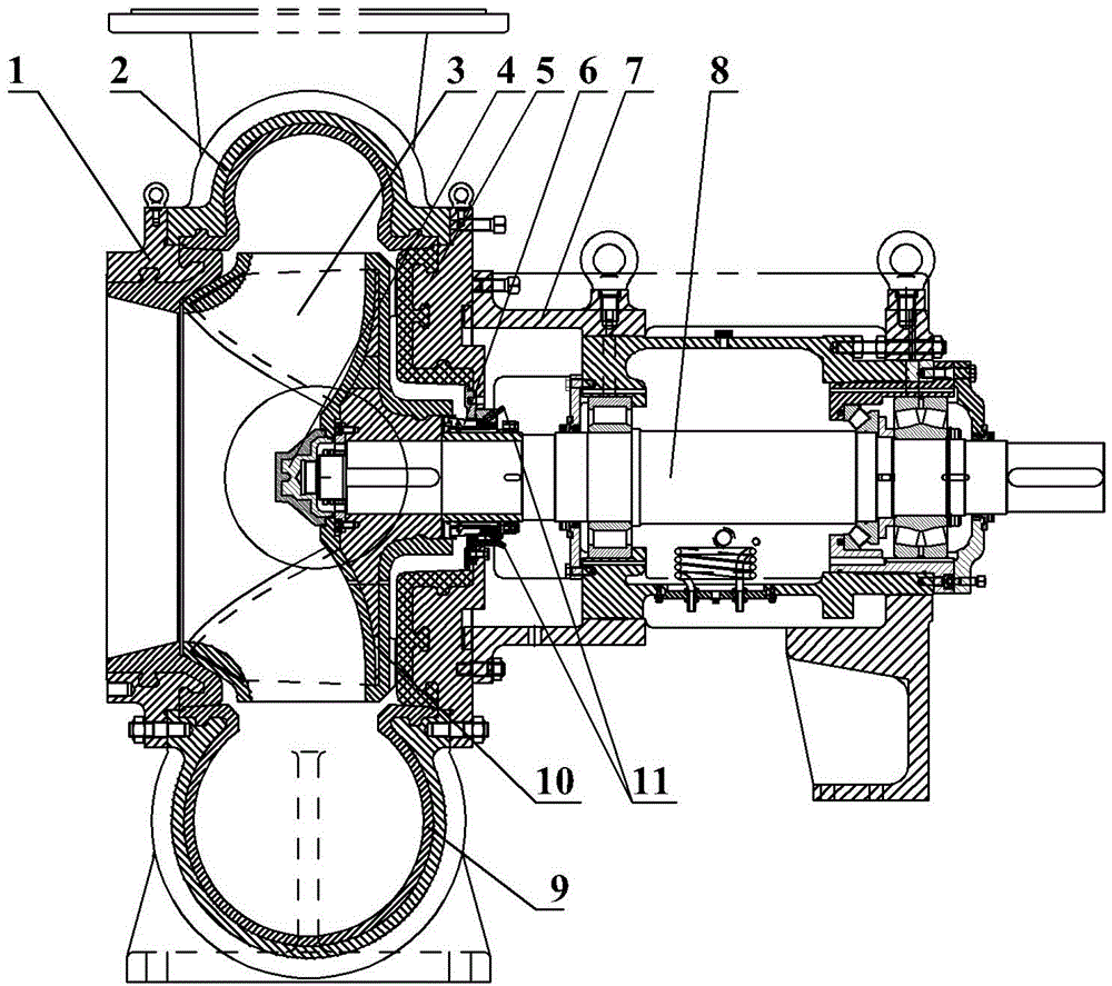
The invention provides a silicon carbide ceramic lined desulphurization pump and specifically relates to a centrifugal pump which is manufactured so that a pump case liner and an impeller are made of an integrated silicon carbide ceramic material or the impeller is lined with a ceramic material of a metal framework and which has wear-resisting and corrosion-resisting characteristics; the silicon carbide ceramic lined desulphurization pump is applied to a flue gas desulphurization system and used for conveying a slurry or other highly abrasive and highly corrosive solutions. The invention provides a centrifugal ceramic desulphurization pump in which a metal housing and a silicon carbide ceramic liner are integrated closely and integrally, and an impeller is made of the integrated silicon carbide ceramic material, and which is corrosion-resistant, and a manufacturing process of the centrifugal ceramic desulphurization pump. The centrifugal ceramic desulphurization pump comprises a pump body with a spiral volute chamber, and is characterized in that the pump body is lined with ceramics, an impeller nut is provided with a ceramic layer, the impeller is integrally made of the ceramics, a front cover plate core bar is arranged in the front cover plate of the impeller, while a rear cover plate core bar is arranged in the rear cover plate of the impeller, and a blade core bar is arranged in a blade of the impeller.

Description

technical field [0001] The invention relates to a centrifugal pump, in particular to a centrifugal pump which is made of integral silicon carbide ceramic material or impeller lining metal skeleton ceramic material, and is wear-resistant and corrosion-resistant; it is used for smoke The gas desulfurization system transports slurry or other strong abrasive and strong corrosive solutions. Background technique [0002] The desulfurization pump is a centrifugal slurry pump, mainly used in wet flue gas desulfurization devices. Wet desulfurization technology is the most widely used and mature technology in the world, and the desulfurization efficiency can reach over 95%. The desulfurization pump as the slurry circulation pump is the key equipment in the flue gas desulfurization device. [0003] In the wet flue gas desulfurization device, the medium transported by the pump is limestone slurry or gypsum slurry. The pH of the medium in the slurry is pH=4.0-9.0, which is generally ac...

Claims


Application Information

Patent Timeline
IPC IPC(8): F04D7/06F04D29/02C04B35/584C04B35/622
Inventor 宋景尧郭敏韩毅张景云袁宗久于晓滨高殿志邹云祥崔韧马士季刘啸董明刘振宇曹圣东范汇超路建民
Owner SHENYANG FIRST PUMP CO LTD
Learn More