
Agitated fluidized bed type drying machine

A technology of agitated flow and dryer, applied in hearth furnaces, drying solid materials, heating to dry solid materials, etc., can solve the problem of inability to maintain consistent particle size, damage to nutritional factors and biological activity, and different residence times. question

Active Publication Date: 2014-08-06
孙甫兴
View PDF5 Cites 2 Cited by
  • Summary
  • Abstract
  • Description
  • Claims
  • Application Information

AI Technical Summary

Problems solved by technology

When the airflow dryer is used to dry the biologically fermented feed, because the particle size of the feed entering the drying cylinder cannot be kept consistent, the residence time of the feed particles in the high-temperature drying cylinder is different, and the feed particles with a long residence time The temperature itself may exceed the temperature at which it maintains the nutritional factors and biological activities formed during the biological fermentation process, thereby destroying its nutritional factors and biological activities

Method used


Image

  • Agitated fluidized bed type drying machine
  • Agitated fluidized bed type drying machine
  • Agitated fluidized bed type drying machine

Examples


Embodiment Construction

[0016] The stirring fluidized bed dryer of the present invention will be further described in detail in conjunction with the accompanying drawings.

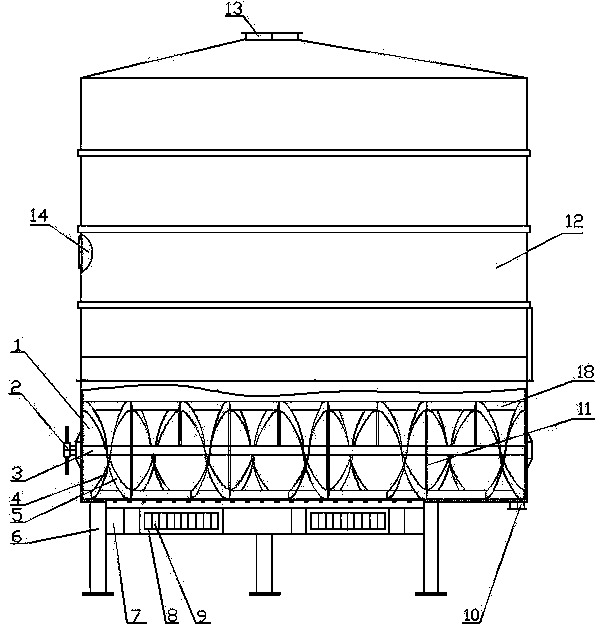
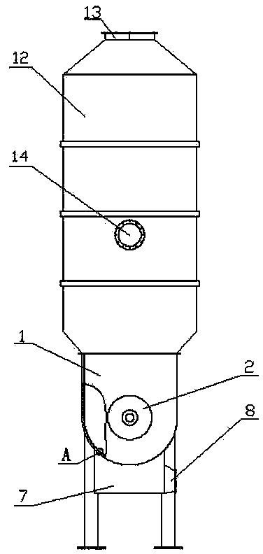
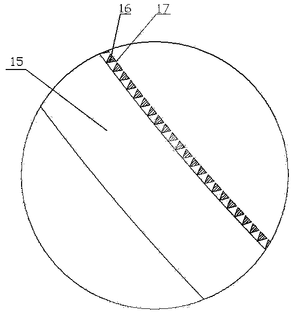
[0017] Such as figure 1 , figure 2 with image 3As shown, the stirring fluidized bed dryer of the present invention includes a drying chamber 1, the upper part of the drying chamber 1 is a rectangular box, and the lower part of the drying chamber 1 is a semi-cylindrical box that is arranged horizontally and protrudes downwards. The lower end of the box body and the upper end of the semi-cylindrical box body are both open and of the same size, and the rectangular box body and the semi-cylindrical box body are connected up and down to form the drying chamber 1 . An air inlet chamber 7 is connected to the bottom of the drying chamber 1 close to one end thereof, and the connection between the drying chamber 1 and the air inlet chamber 7 is densely covered with drying holes 17 . The groove wall of the semi-cylindrical box of the d...


PUM


Abstract

The invention relates to an agitated fluidized bed type drying machine. The agitated fluidized bed type drying machine comprises a drying chamber, wherein the lower portion of the drying chamber is connected with an air inlet chamber; a hot wind inlet is formed in the air inlet chamber; drying holes are densely distributed in the position where the drying chamber and the air inlet chamber are connected. An agitating shaft is arranged inside the drying chamber; the two ends of the agitating shaft and the two ends of the drying chamber are in rotating fit; one end of the agitating shaft extends out and is connected with a drive sprocket. The position, inside the drying chamber, of the agitating shaft is provided with banded propulsion leaves which are continuously arranged. The outer edges of the banded propulsion leaves are evenly provided with knockout plates in the circumferential direction of the agitating shaft. The upper end of the drying chamber is open and is connected with an upper tank, the side wall of one end, corresponding to the air inlet chamber, of the upper tank is provided with a feed port, the end, away from the air inlet chamber, of the bottom of the drying chamber is provided with a discharge port, and the top of the upper tank is provided with an air outlet. When the agitated fluidized bed type drying machine dries biological fermentation feed, the drying efficiency is high, drying is even, and nutrient factors and biological activity of the biological fermentation feed are not destroyed when the biological fermentation feed is dried.

Description

technical field [0001] The invention relates to a drying machine, in particular to a stirring fluidized bed drying machine for drying heat-sensitive materials with high humidity, and is especially suitable for drying biological fermented feed. Background technique [0002] It is known in the industry of producing feed that the feed produced by the biological fermentation method usually needs to be dried in order to store for a long time. [0003] At present, belt dryers, fluidized bed or airflow dryers are usually used in the industry to dry biologically fermented feed. The belt dryer usually includes a feeding device, a conveyor belt and a heating device. When working, the material to be dried is evenly added to the conveyor belt by the feeding device, and the heating device heats and dries the material during the conveying process of the conveyor belt. When using a belt dryer to dry biologically fermented feed, since the feed is in a relatively static state during the for...

Claims


Application Information

Patent Timeline
Patent Type & Authority Applications(China)
IPC IPC(8): F26B3/092F26B25/04F26B25/02
Inventor 孙甫兴
Owner 孙甫兴
Learn More