Hydraulic drive percussion drilling tool

A drilling tool and hydraulic impact technology, which is applied to drilling equipment, driving devices for drilling in wellbore, and earth-moving drilling and mining, etc., can solve the problems of short hammer stroke, complex structure, and short hammer acceleration time.

Active Publication Date: 2014-08-06
BEIJING INFORMATION SCI & TECH UNIV +1
View PDF6 Cites 5 Cited by
  • Summary
  • Abstract
  • Description
  • Claims
  • Application Information

AI Technical Summary

Problems solved by technology

These problems and defects are related to the structure of the existing percussion drilling tools, mainly including complex structure, many wearing parts, short stroke of the hammer, short service life, low stability and reliability, etc. These problems limit Popularization and Application of Rotary Percussion Drilling Technology in Petroleum Drilling Industry
For example, the YSC-178 jet impactor developed by Changchun University of Science and Technology has a small inner diameter of the jet hole. During work, high-pressure drilling fluid passes through the jet hole at high speed, and the particles in the drilling fluid will cause erosion and wear of the jet hole, resulting in life Another example: the SYZJ type double-acting impactor developed by China University of Petroleum has a short stroke of the hammer and a short time for the acceleration of the hammer, and the hydraulic impact force driving the movement of the hammer is very large, which is easy to cause Fatigue damage at the connection to the piston, reducing tool life

Method used


Image

  • Hydraulic drive percussion drilling tool
  • Hydraulic drive percussion drilling tool
  • Hydraulic drive percussion drilling tool

Examples


Embodiment Construction

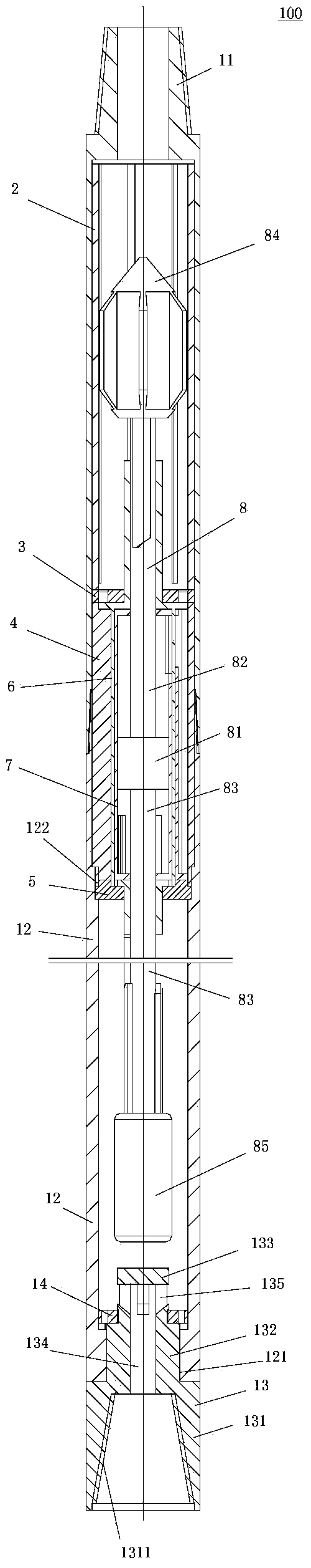
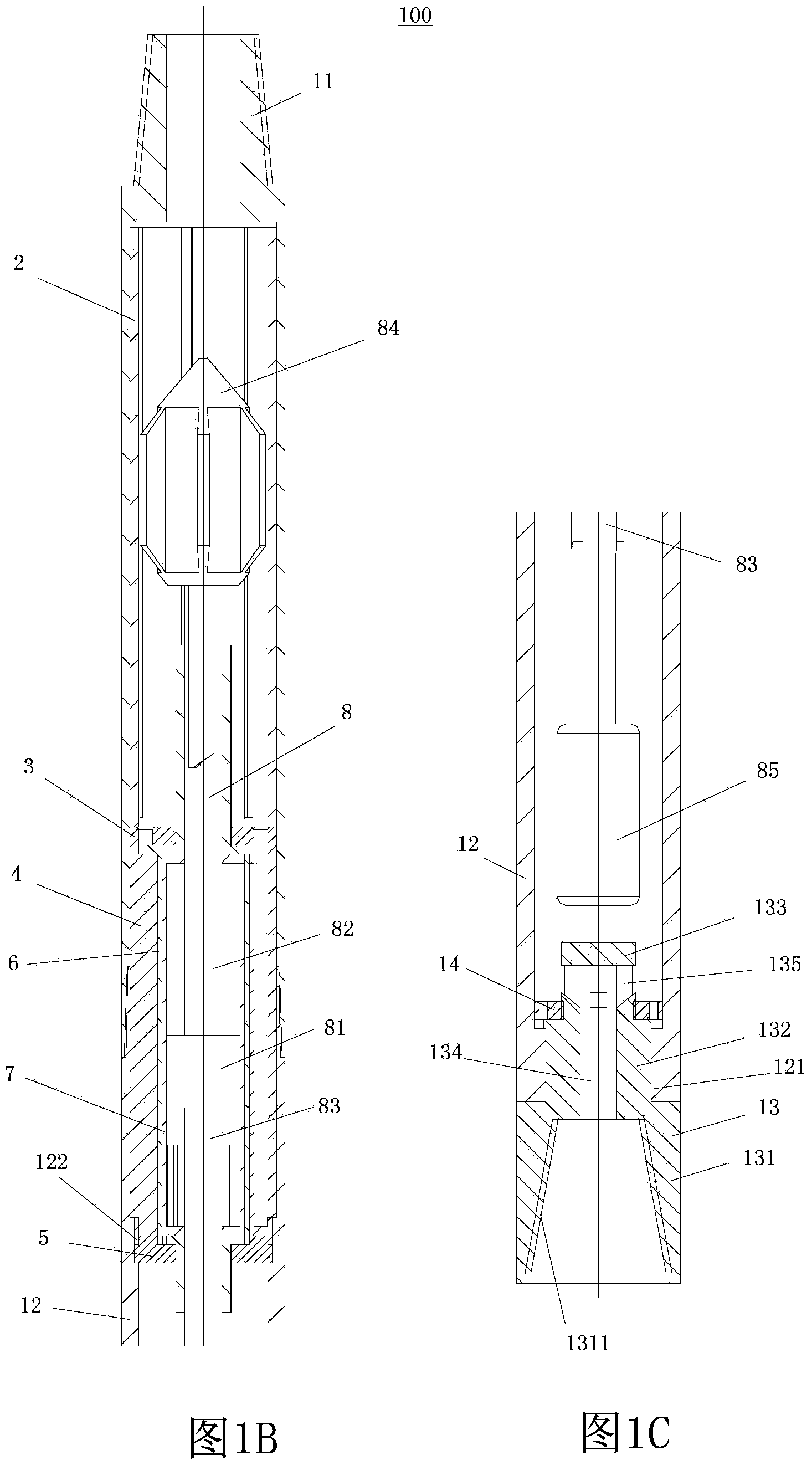
[0032] In order to have a clearer understanding of the technical features, purposes and effects of the present invention, the specific implementation manners of the present invention will now be described with reference to the accompanying drawings.

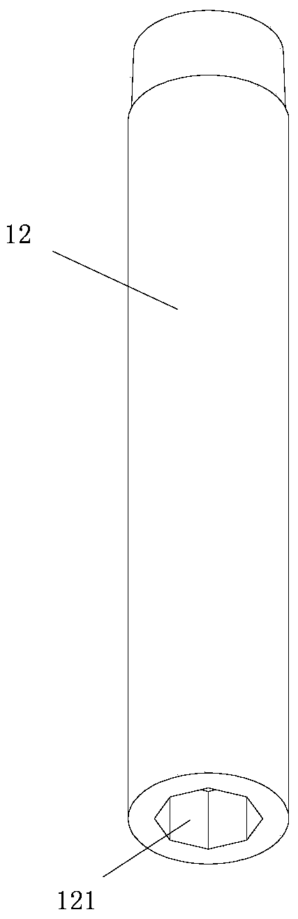
[0033] Such as Figure 1A , Figure 1B , Figure 1C As shown, the present invention proposes a hydraulic percussion drilling tool 100, the drilling tool 100 includes an upper sub-section 11 and a connecting sub-section 12 fixedly connected to the lower end of the upper sub-section 11; the upper sub-section 11 is cylindrical, The upper end is a taper threaded male buckle connected to the drill pipe, and the lower end is a tapered threaded box joint connected to the connecting nipple 12, and the inside is a hollow structure; figure 2 As shown, the connecting short joint 12 is also cylindrical, the upper end is a tapered thread connecting the upper short joint 11, the lower end is provided with a through hole 121 with an octagonal...


PUM


Abstract

The invention discloses a hydraulic drive percussion drilling tool. A cylinder composed of an upper short section and a connection short section is internally, sequentially and fixedly provided with a guiding sleeve, an upper end cover, a guide cylinder and a lower end cover from top to bottom. A diverter is arranged in the guide cylinder in a swinging mode, and a cylinder body is arranged in the diverter. A punch hammer assembly is arranged in the cylinder composed of the upper short section and the connection short section in a sliding mode and comprises a piston, an upper piston rod and a lower piston rod, wherein the piston is arranged in the cylinder body in a sliding mode and the piston comprises the upper piston rod and the lower piston rod. A drill seat is circumferentially and fixedly arranged at the bottom end of the connection short section in a hanging mode, and a first cam mechanism is arranged between the upper piston rod and the diverter. A second cam mechanism is arranged between the lower piston rod and the diverter. Liquid flow distribution channels communicated with the cylinder body are formed in the guide cylinder and the cylinder body, and flow distribution holes communicated with the corresponding flow distribution channels are formed in the diverter. The flowing direction of fluid entering the cylinder body changes intermittently due to forward swinging and reverse swinging of the diverter, and therefore the punch hammer assembly is driven to move in a reciprocating mode from top to bottom. According to the hydraulic drive percussion drilling tool, the reversing stability of a punch hammer can be improved, the service life is prolonged, and the rock breaking effect and working efficiency are improved.

Description

technical field [0001] The invention relates to a downhole drilling tool in the field of petroleum development, in particular to a hydraulic percussion drilling tool. Background technique [0002] Modern conventional drilling mainly adopts rotary drilling technology. When drilling hard or abrasive formations, the drilling speed of drilling machinery will decrease, which will greatly increase the cost of drilling. However, when drilling horizontal wells or extended-reach wells, due to friction and other factors, it is difficult for the drilling tool to run into the well, and the WOB cannot be loaded or partially loaded on the drill bit, which seriously affects the stability of the drilling system and drilling costs. [0003] Rotary percussion drilling technology is an effective method to solve the above problems at present. The method is to add an impact drilling tool to the upper part of the drill bit. The principle is: when drilling, high-pressure gas or drilling fluid push...

Claims


Application Information

Patent Timeline
Patent Type & Authority Applications(China)
IPC IPC(8): E21B4/16
Inventor 柳贡慧查春青李玉梅
Owner BEIJING INFORMATION SCI & TECH UNIV
Why Eureka
Try Eureka