
Waterproof cable well

A waterproof cable and well body technology, applied in water conservancy projects, underwater structures, artificial islands, etc., can solve the problems of reducing the continuous use effect of cables and increasing labor costs

Active Publication Date: 2014-07-30
NINGHAI COUNTY POWER EQUIP BUILD OR REPAIR FACTORY +1
View PDF7 Cites 9 Cited by
  • Summary
  • Abstract
  • Description
  • Claims
  • Application Information

AI Technical Summary

Problems solved by technology

[0006] The technical solutions disclosed above all only use structural improvement to strengthen the waterproofing of the cable well, but none of them drain the water in time and continuously, and all of them need to manually drain the water after detecting the accumulated water, which increases labor costs and reduces Therefore, at present, it is difficult to achieve the effect of waterproofing and dehumidification inside the cable shaft at the same time only by improving the structure

Method used


Image

  • Waterproof cable well
  • Waterproof cable well

Examples


Embodiment 1

[0029] The components and parts by weight of the water-repellent coating in this embodiment are: 60 parts of polyether (polyethylene glycol ether), 6 parts of epoxy resin, 10 parts of polytetrafluoroethylene, 10 parts of polyether ether ketone, plasticized 0.5 parts of agent (dioctyl phthalate), 10 parts of polyurethane (polyurethane), 1 part of simethicone, 5 parts of nano silicon dioxide, and 30 parts of ethanol (40%).

[0030] The preparation method of the above-mentioned water-repellent coating in this embodiment, the specific steps include:

[0031] (4) First mix the polyether (polyethylene glycol ether), epoxy resin, polytetrafluoroethylene, polyether ether ketone, and plasticizer in the proportion of the formula, and then stir and mix at 80-160 ° C for 2-2.5 h;

[0032] (5) Mix polyurethane, simethicone, nano-silica, and ethanol according to the formula ratio, then heat and reflux for 6-7 hours;

[0033] (6) Mix the materials obtained in step (1) and step (2), and the...

Embodiment 2

[0035] The components and parts by weight of the water-repellent coating in this embodiment are: 85 parts of polyether (polyethylene glycol ether), 5 parts of epoxy resin, 12 parts of polytetrafluoroethylene, 12 parts of polyetheretherketone, plasticized Agent (diisooctyl phthalate) 1.5 parts, polyurethane (polyurethane) 12 parts, simethicone 2 parts, nano silicon dioxide 6 parts, ethanol (20-60%) 40 parts.

[0036] The preparation method is the same as in Example 1.

[0037] During construction, use conventional mechanical spraying, brushing, etc. to coat the inner surface of the cable well.

[0038] Above-mentioned coating performance of the present invention is as shown in table 1 below:

[0039] Table 1 Coating performance of the embodiment of the present invention

[0040]

[0041]It can be seen from the above table that the present invention has good water repellency, is not easy to permeate water, and has strong adhesion to the inner surface of the well.


PUM

PropertyMeasurementUnit
particle diameteraaaaaaaaaa

Abstract

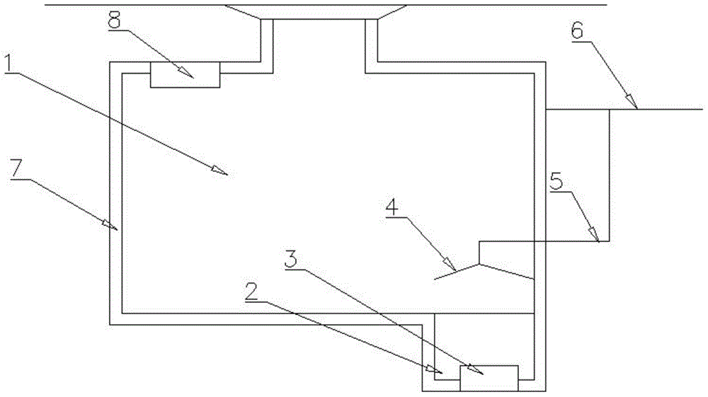
The invention discloses a waterproof cable well, which comprises a well body, wherein the low-lying area at the well bottom of the well body is provided with a sump; the top face of the well body is provided with a fan heater; the fan heater comprises a humidity sensor; the sump is internally provided with an ultrasonic atomization device; a mist collecting hood is arranged above the sump; a suction pipe and an exit pipe of the mist collecting hood are communicated; repellent paint is painted on the inner surface of the well body; the components and the weight parts of the repellent paint is as follows: 50-100 parts of polyether, 5-8 parts of epoxy resin, 5-15 parts of polytetrafluoroethylene, 5-15 parts of polyether ether ketone, 0.5-1.5 parts of plasticizer, 10-15 parts of polyurethane, 1-5 parts of simethicone, 5-10 parts of nanometer silicon dioxide and 30-50 parts of ethanol. The waterproof cable well has the advantages that the waterproof cable well is capable of draining water continuously and timely in a rainy humid environment, and the waterproof and dehumidification performances are realized.

Description

technical field [0001] The invention relates to the technical field of cable matching devices, in particular to a waterproof cable well. Background technique [0002] When the cable line is laid, a cable well must be set at a certain distance. The importance of the cable line does not need to be repeated, and the waterproof of the cable well has a great influence on the stability of the cable line. Since the cable well is often set under the ground , the surface temperature inside the well is lower than the ambient temperature. In the case of excessive humidity, it will cause severe condensation water corrosion and seriously affect the power cable; in addition, in a rainy and humid environment, the cable well is continuously intruded by water. , although the amount is not much, the water in the cable well cannot be drained in time and continuously, and the cable well is prone to high humidity. [0003] Existing patent documents, for example, the Chinese patent application w...

Claims


Application Information

Patent Timeline
Patent Type & Authority Applications(China)
IPC IPC(8): E02D29/12C09D171/08C09D163/00C09D127/18C09D161/16C09D175/04C09D183/04C09D7/12
Inventor 周磊储海峰钱锡颖舒建华王斌谢敏霞
Owner NINGHAI COUNTY POWER EQUIP BUILD OR REPAIR FACTORY
Learn More