
Manufacturing method of LED fluorescent lamp tube

A technology of LED fluorescent lamp and manufacturing method, which is applied in the direction of light source, lampshade, point light source, etc., can solve the problems of high packaging cost and application cost, low light transmittance of lampshade, cumbersome manufacturing process, etc. Light effect, the effect of saving material cost

Active Publication Date: 2014-07-23
陕西电子信息集团光电科技有限公司
View PDF6 Cites 0 Cited by
  • Summary
  • Abstract
  • Description
  • Claims
  • Application Information

AI Technical Summary

Problems solved by technology

[0003] However, traditional LED fluorescent tubes generally use small and medium power TOP light source chip packaging, and the light transmittance of the lampshade is low, the light efficiency is low, the thermal resistance is large, the packaging cost and application cost are high, and the manufacturing process is cumbersome.

Method used


Image

  • Manufacturing method of LED fluorescent lamp tube
  • Manufacturing method of LED fluorescent lamp tube
  • Manufacturing method of LED fluorescent lamp tube

Examples


Embodiment Construction

[0040] The present invention will be described in detail below in conjunction with the accompanying drawings and specific embodiments.

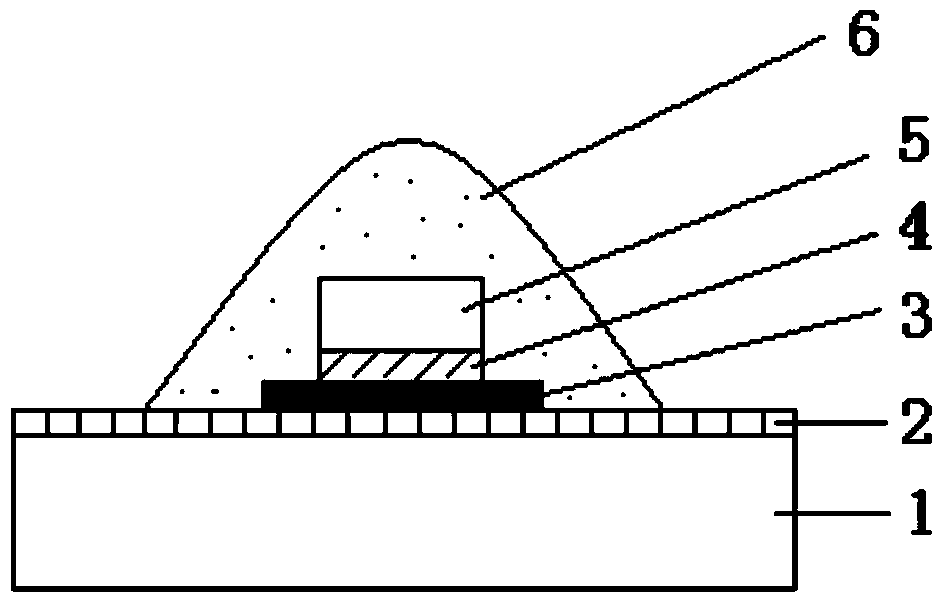
[0041] see figure 1 , a method for manufacturing a novel fluorescent tube provided by an embodiment of the present invention includes manufacturing a panel-type LED light source and manufacturing a fluorescent tube.

[0042] First, make the panel LED light source:

[0043] First, use other chemical methods such as electroplating or sputtering to plate pure tin or gold-tin alloy on the bottom of the sapphire substrate of the flip chip 5 as the coating 4 on the bottom of the flip chip on the contact surface with the aluminum substrate. The power of 5 is 1-3W, and the coating thickness is 0.2-1μm.

[0044] Second, the upper surface of the aluminum substrate 1 is plated with gold or silver as the eutectic layer 2, and the thickness of the eutectic layer is basically equivalent to the thickness of the plating layer at the bottom of the flip chip...


PUM

PropertyMeasurementUnit
Coating thicknessaaaaaaaaaa
Roughnessaaaaaaaaaa
Thicknessaaaaaaaaaa

Abstract

The invention discloses a manufacturing method of an LED fluorescent lamp tube. The method includes the steps of (1) manufacturing of a plate-type LED light source and (2) manufacturing of the LED fluorescent lamp tube. Manufacturing of the plate-type LED light source includes the steps that a bottom plating layer is plated on a flip chip substrate, gold or silver is plated on an aluminum substrate to serve as an eutectic layer, a solder is welded on the surface of the eutectic layer in a spot mode, a flip chip is placed on the solder, the eutectic layer of the aluminum substrate is heated, and after the solder is dissolved, the flip chip is welded onto the aluminum substrate; a LENS structure is manufactured on the aluminum substrate with the flip chip, and manufacturing of the plate-type LED light source for the LED fluorescent lamp tube is completed. Manufacturing of the fluorescent lamp tube comprises the steps that a lampshade is selected, and surface roughening is conducted on the lampshade; a layer of optical anti-reflection film is manufactured on a surface roughing layer of the lampshade; the plate-type LED light source is placed under the lampshade, and after a radiator and a power supply are arranged on lower portion of the plate-type LED light source, the LED lamp tube is assembled. The LED fluorescent lamp tube is low in packaging cost, low in application cost, low in heat resistance, high in light transmittance, high in brightness, good in reliability and capable of being assembled and applied conveniently.

Description

technical field [0001] The invention belongs to the technical field of semiconductor device packaging, and relates to a method for manufacturing a novel LED fluorescent tube. Background technique [0002] LED fluorescent tubes have become a trend of indoor lighting in the 21st century. LED fluorescent tubes are characterized by high quality, durability, energy saving and environmental protection, and have become the mainstream in the field of lighting. The projection angle of LED fluorescent tubes has a wide range of adjustment. The brightness of 15W is equivalent to that of ordinary 40W fluorescent lamps. The power saving is as high as 80%, and the service life is more than 10 times that of ordinary fluorescent tubes. It is almost maintenance-free. The problem of starter and starter. [0003] However, traditional LED fluorescent tubes are generally packaged with small and medium power TOP light sources, and the light transmittance of the lampshade is low, the light efficie...

Claims


Application Information

Patent Timeline
IPC IPC(8): H01L33/00H01L33/48H01L33/64H01L33/58H01L33/62
CPCF21V3/04F21V19/002F21Y2101/00H01L33/62
Inventor 高璇童华南李涛田仿民慈和安于浩
Owner 陕西电子信息集团光电科技有限公司
Learn More